Electromagnetic actuator

A technology of electromagnetic actuators and permanent magnets, which is applied in the direction of circuits, magnets, electromechanical devices, etc., and can solve problems such as actuator performance changes

Inactive Publication Date: 2016-02-03
DENSO CORP
View PDF7 Cites 8 Cited by
  • Summary
  • Abstract
  • Description
  • Claims
  • Application Information

AI Technical Summary

Problems solved by technology

As a result, metallic foreign objects are attracted by the permanent magnets, and the actuator may have performance changes due to this

Method used


Image

  • Electromagnetic actuator
  • Electromagnetic actuator
  • Electromagnetic actuator

Examples


Embodiment Construction

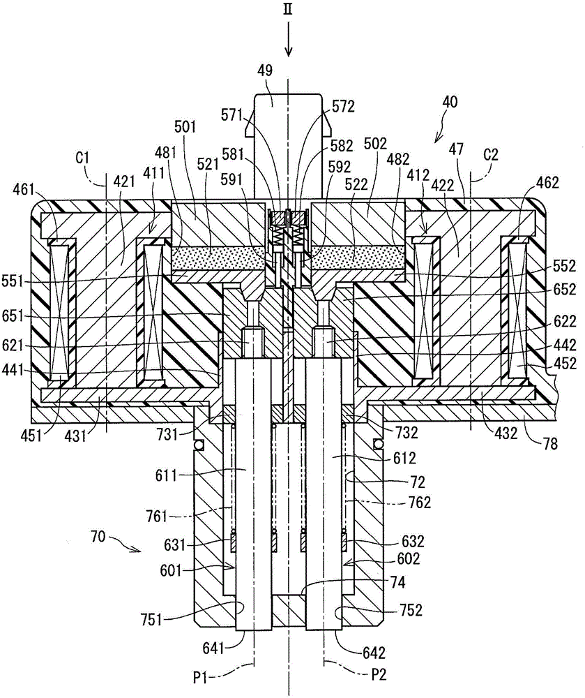
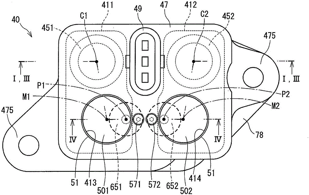
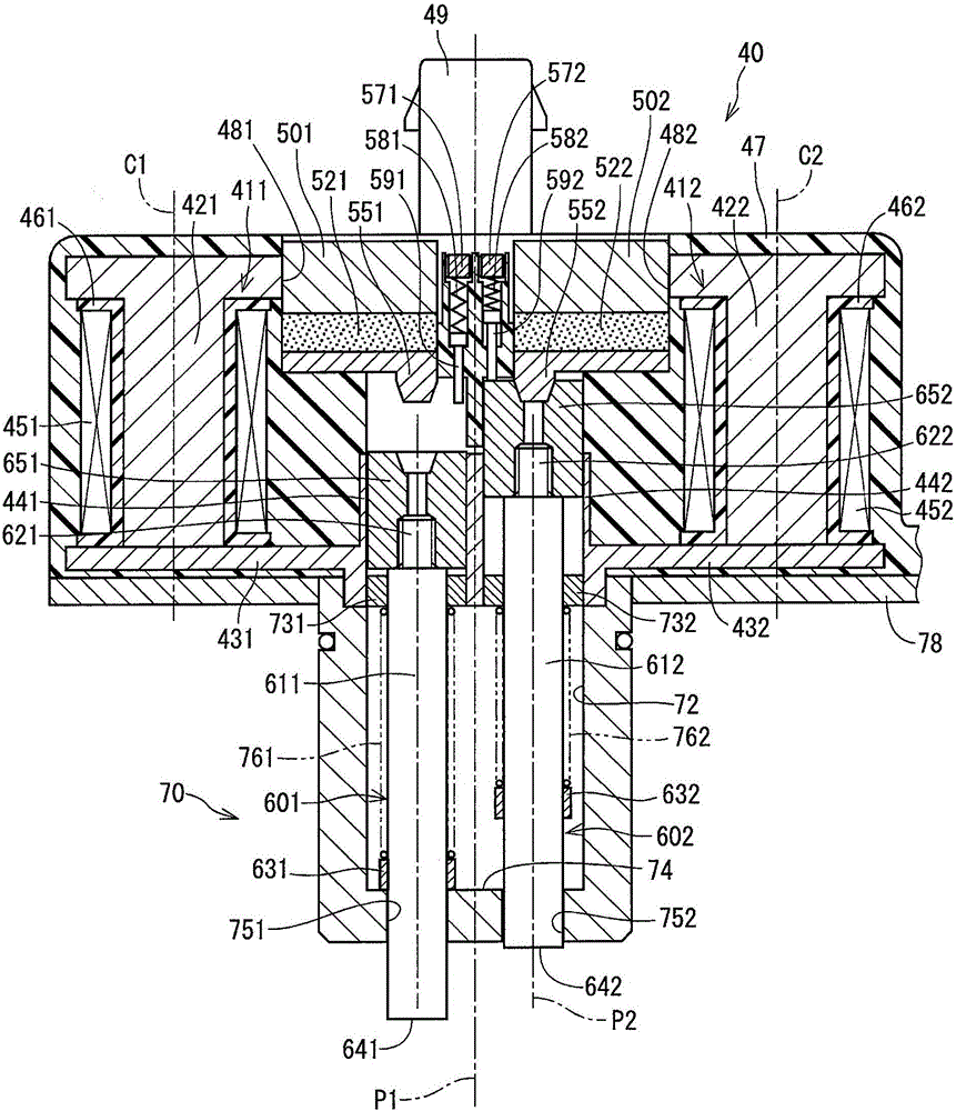
[0017] An electromagnetic actuator according to an embodiment will be described below with reference to the drawings. As described in JP2013-258888A, the electromagnetic actuator is applied to a valve lift adjusting device for adjusting the lift amount of an intake valve or an exhaust valve of an internal combustion engine by means of a cam integrally provided with a slider , the slider rotates with the camshaft.

[0018] The slider of the valve lift adjusting device is arranged to rotate together with the camshaft and can move axially relative to the camshaft, and includes an engagement groove on its outer periphery whose axial position gradually changes according to the rotation angle. Change. Based on a command from the control device, the electromagnetic actuator advances the "operation-side restricting pin" (which is either one of the two restricting pins) to engage the end of the operating-side restricting pin with the engagement groove of the slider. Therefore, the sl...


PUM


Abstract

The invention provides an electromagnetic actuator. A coil (451,452) generates a magnetic flux (Phi 1) in the opposite direction of either of first and second permanent magnets (521,522) so as to reduce magnetic attraction for attracting corresponding plunger pistons (651,652). First and second advance springs (761,762) operate in an advance direction through push force; when the coil (451,452) is powered on, either of a first/second pin (601,602) on the side with smaller magnetic attraction is used as an operation side limiting pin. When the corresponding plunger pistons (651,652) are attracted to a preset distance of corresponding permanent magnets (521,522), obstruction components (591,592) and the corresponding plunger pistons (651,652) are in contact to resist backstep. A resistance push portion (581,582) applies a resistive load in the direction of resisting permanent magnet attraction to the obstruction components (591,592). A load adjusting portion (571,572) can adjust the resistive load of the resistance push portion (581,582).

Description

technical field [0001] The present disclosure relates to an electromagnetic actuator applied to a valve lift adjusting device of an internal combustion engine, and facilitates engagement of a limiting pin with an engagement groove to switch between positions of a slider. Background technique [0002] Conventionally, for a valve lift adjustment device that adjusts the lift amount of an intake valve or an exhaust valve of an internal combustion engine, a device is known that switches between the positions of a slider that is arranged to follow the camshaft Rotate together and be able to move axially relative to the camshaft. As means for switching between the positions of the slider, there is known an electromagnetic actuator which selectively operates one of two restraint pins according to the displacement direction of the slider so that the end of the restraint pin fits into the position of the slider. Formed in the engaging groove in the slider. [0003] An electromagneti...

Claims


Application Information

Patent Timeline
Patent Type & Authority Applications(China)
IPC IPC(8): F16K31/08
CPCH02K33/02F01L2013/0052F01L2820/031H01F7/1607F16K31/082
Inventor 天野均
Owner DENSO CORP
Why Eureka
Try Eureka