
Touch device and touch sensing method thereof

A touch device, touch sensing technology, applied in the direction of instrument, electrical digital data processing, data processing input/output process, etc., can solve interpretation errors, use convenience to be improved, scanning unit and optical sensor Time-consuming and labor-intensive problems to achieve the effect of solving ghost problems

Inactive Publication Date: 2016-02-10
CORETRONIC
View PDF8 Cites 0 Cited by
  • Summary
  • Abstract
  • Description
  • Claims
  • Application Information

AI Technical Summary

Problems solved by technology

However, the control unit obtains the positions of the touch tools 808 and 810 by calculating the intersection points between the scanning beams, so the control unit may also regard the intersection points 812 and 814 of the scanning beams as the positions of the touch tools, resulting in misjudgment , the intersection 812 and 814 form the so-called ghost point
In addition, when the optical touch technology is applied to a large-area screen such as an electronic whiteboard or a wall, the installation of the scanning unit and the optical sensor is often time-consuming and labor-intensive, and optical calibration is required after the installation is completed, so it is convenient to use still needs to be improved

Method used


Image

  • Touch device and touch sensing method thereof
  • Touch device and touch sensing method thereof
  • Touch device and touch sensing method thereof

Examples


Embodiment Construction

[0027] The aforementioned and other technical content, features and effects of the present invention will be clearly presented in the following detailed description of a preferred embodiment with reference to the accompanying drawings. The directional terms mentioned in the following embodiments, such as: up, down, left, right, front or back, etc., are only referring to the directions of the drawings. Accordingly, the directional terms are used to illustrate and not to limit the invention.

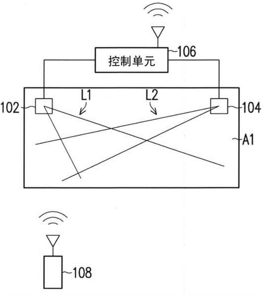
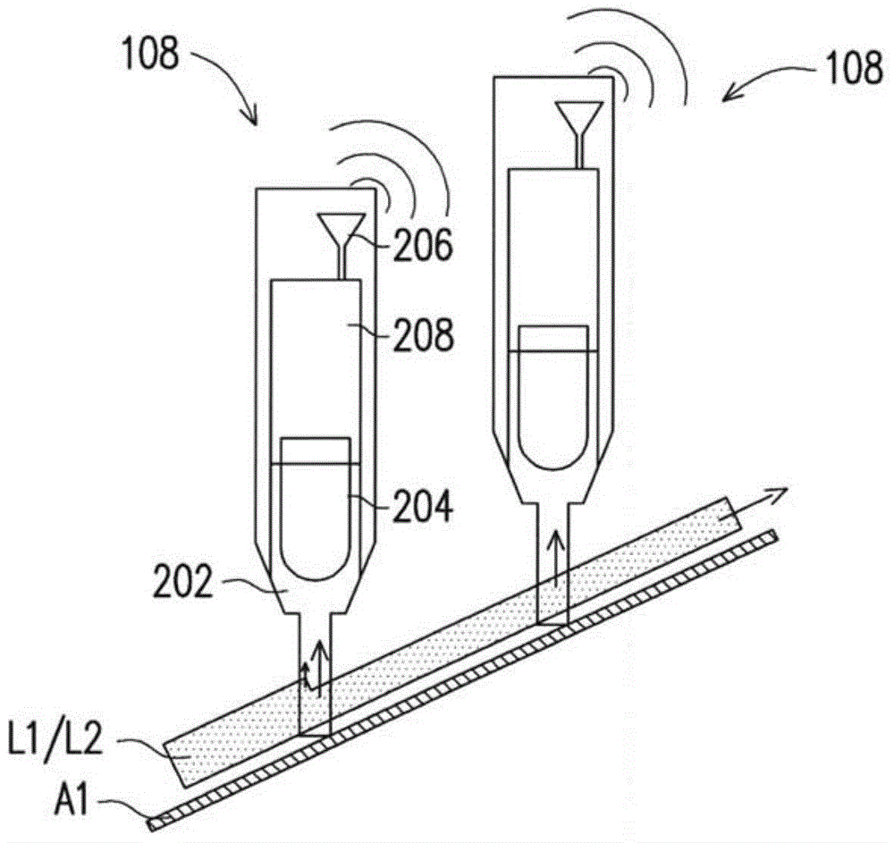
[0028] figure 1 For a schematic diagram of a touch device according to an embodiment of the present invention, please refer to figure 1 . The touch device includes a scanning unit 102 , a scanning unit 104 , a control unit 106 and a touch tool 108 , and the control unit 106 is coupled to the scanning unit 102 and the scanning unit 104 . The control unit 106 can respectively control the scanning unit 102 and the scanning unit 104 to send out the scanning light beam L1 and the scanning ...


PUM


Abstract

The invention provides a touch device and a touch sensing method thereof. Touch information produced according to received scanning light beams is initiatively transmitted back by a touch tool, and coordinates of the touch tool in a touch area are calculated according to the touch information which are transmitted back.

Description

technical field [0001] The present invention relates to an electronic device, and in particular to a touch device and a touch sensing method thereof. Background technique [0002] Generally speaking, the optical touch technology uses a light source and an optical sensor on the edge of the screen. ) reflected part of the light, and then determine the touch position according to the sensing result of the optical sensor. Although the known optical touch technology can effectively determine the touch position of a single touch point, when multiple touch tools are used for multi-touch at the same time, problems of blind spots and ghost points will appear. [0003] Figure 8A and Figure 8B It is a schematic diagram of a known touch device. Please refer to Figure 8A , the known touch device scans the touch area C1 through scanning beams emitted by the scanning units 802 and 804, when the scanning beam emitted by the scanning unit 802 touches the touch tool 808 in the touch are...

Claims


Application Information

Patent Timeline
Patent Type & Authority Applications(China)
IPC IPC(8): G06F3/042G06F3/0354G06F3/038
CPCG06F3/0325
Inventor 郭本宁杨忠隆陈勇志
Owner CORETRONIC
Learn More