Touch-control system and method for touch detection
A touch system and touch technology, applied in the direction of instruments, electrical digital data processing, data processing input/output process, etc., can solve the problem that the actual position of the pointer cannot be correctly judged
- Summary
- Abstract
- Description
- Claims
- Application Information
AI Technical Summary
Problems solved by technology
Method used
Image
Examples
no. 1 example
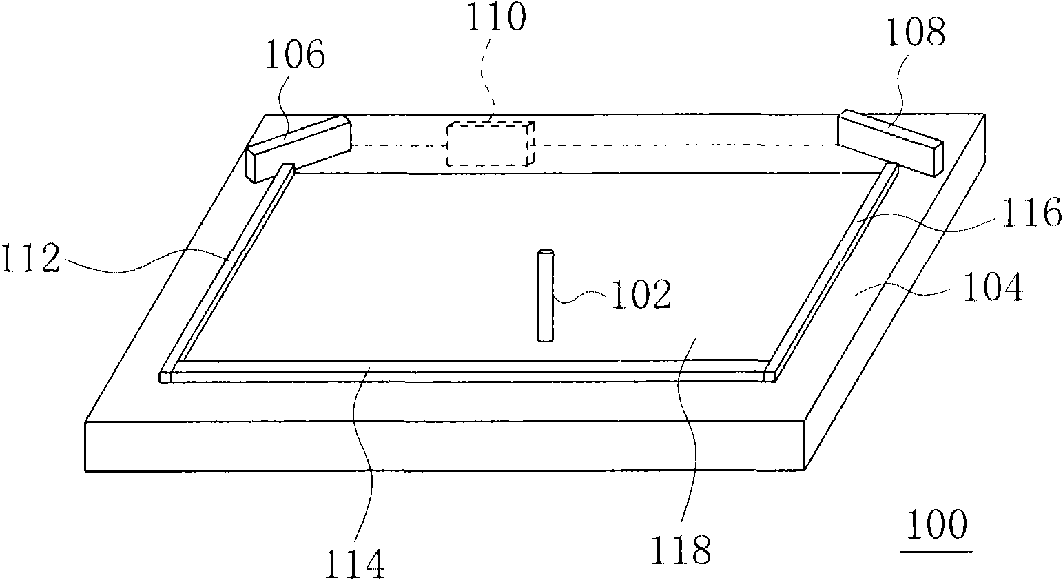
[0033] The touch system proposed in this embodiment can be reused figure 1 The perspective view shown is for illustration. please refer again figure 1 , in this embodiment, the panel 104 is replaced by a touch panel, and the operation mode of the processing circuit 110 is modified. The touch panel has a touch surface (described in detail later), and the touch panel adopts a touch detection structure, and the touch detection structure is mainly composed of a plurality of horizontal wires arranged in parallel and a plurality of parallel wires. formed by vertical wires, and each horizontal wire is perpendicular to each vertical wire. These horizontal wires are not electrically coupled to any vertical wires, only when the pointer (or other objects) touches the touch surface, the horizontal wires and the vertical wires corresponding to the touch position of the pointer are electrically coupled. In addition, the horizontal wires and the vertical wires are electrically coupled to ...
no. 2 example
[0042] This embodiment proposes another touch system. The difference between this touch system and the touch system of the first embodiment is that the touch panel of this touch system adopts another touch detection structure. The touch detection structure is mainly composed of a plurality of longitudinal wires arranged in parallel. This touch system is detected by Figure 6 to illustrate.
[0043] Figure 6 An explanatory diagram of the touch system of this embodiment performing multi-touch, which takes two-point touch as an example. exist Figure 6 In, the label and figure 1 The same reference numerals in the reference numerals represent the same object, the reference numeral 404 refers to the longitudinal wire, and the reference numerals 406 and 408 both refer to indicators. In addition, the quadrangular area configured with these longitudinal wires 404 is represented as a touch surface. In this example, the shape of the touch surface is rectangular.
[0044] Such as...
no. 3 example
[0048]This embodiment proposes another touch system. The difference between this touch system and the touch system of the first embodiment is that this touch system only has one image detection device. This touch system is detected by Figure 8 to illustrate.
[0049] Figure 8 An explanatory diagram of the touch system of this embodiment performing multi-touch, which takes two-point touch as an example. exist Figure 8 In, the label and figure 1 The ones with the same number in the above represent the same object, the number 402 refers to the horizontal wire, the number 404 refers to the vertical wire, and the numbers 406 and 408 both refer to the indicator. In addition, the quadrilateral area configured with the horizontal wires 402 and the vertical wires 404 is represented as a touch surface. In this example, the shape of the touch surface is rectangular.
[0050] Such as Figure 8 As shown, the processing circuit 110 detects the above two pointers through the horizo...
PUM
 Abstract
Description
Claims
Application Information
 - R&D Engineer
- R&D Manager
- IP Professional
- Industry Leading Data Capabilities
- Powerful AI technology
- Patent DNA Extraction
Browse by: Latest US Patents, China's latest patents, Technical Efficacy Thesaurus, Application Domain, Technology Topic, Popular Technical Reports.
© 2024 PatSnap. All rights reserved.Legal|Privacy policy|Modern Slavery Act Transparency Statement|Sitemap|About US| Contact US: help@patsnap.com


