Hydraulic jig capable of rapidly switching clamping surfaces

A quick-change, hydraulic clamp technology, used in the field of hydraulic clamps

Inactive Publication Date: 2016-02-24
LUZHOU YUANCHENG ENG MACHINERY CO LTD
View PDF8 Cites 3 Cited by
  • Summary
  • Abstract
  • Description
  • Claims
  • Application Information

AI Technical Summary

Problems solved by technology

[0004] The purpose of the present invention is to provide a hydraulic clamp with fast switching clamping surface, which solves the problem that a single clamp in the prior art cannot clamp both flat and curved surfaces, and achieves the purpose of stabilizing flat or curved workpieces with the same clamp
Aiming at the problem that the existing single clamp can not clamp both flat and curved surfaces, the present invention proposes a hydraulic clamp that quickly switches the clamping surface, through a clamping plate with one side being a plane and the other being a curved surface, and driving the clamping The rotating shaft of the holding plate can realize the convenient and fast replacement of the clamping surface, so as to achieve the purpose of stabilizing the flat workpiece or the curved surface workpiece with the same fixture

Method used


Image

  • Hydraulic jig capable of rapidly switching clamping surfaces
  • Hydraulic jig capable of rapidly switching clamping surfaces
  • Hydraulic jig capable of rapidly switching clamping surfaces

Examples


Embodiment 1

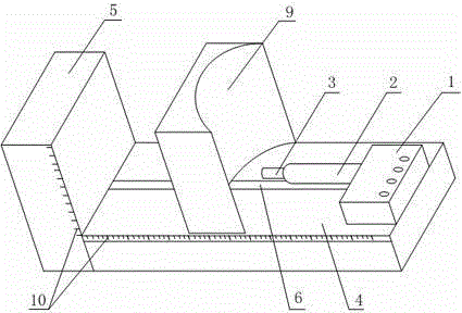
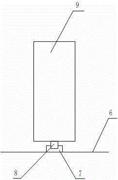
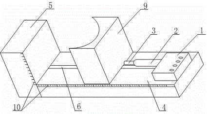
[0017] Such as Figure 1 to Figure 3 The hydraulic clamp with fast switching clamping surface shown includes a base 4, a hydraulic pump 1 arranged on the base 4, a hydraulic cylinder 2 connected to the hydraulic pump 1, and a piston rod connected to the piston inside the hydraulic cylinder 2 3. One end of the base 4 is fixed with a vertical baffle 5, the upper surface of the base 4 is provided with a chute 6, a slider 7 is placed in the chute 6, and a vertical baffle 7 is arranged on the slider 7. A straight rotating shaft 8, on which a clamping plate 9 is fixedly connected, one side of the clamping plate 9 is a plane, and the other side is a curved surface. During the use of this embodiment, the workpiece to be processed is placed at the corner of the base 4 and the baffle 5, the hydraulic pump 1 is started to inject liquid into the hydraulic cylinder 2, the pressure in the hydraulic cylinder 2 rises, and the piston and piston rod are pushed 3 moves forward, the piston rod 3...

Embodiment 2

[0019] Such as Figure 1 to Figure 3 In the shown hydraulic clamp for quickly changing the clamping surface, on the basis of Example 1, the side of the base 4 is provided with a horizontal dimension scale bar 10, and the side surface of the baffle plate 5 is provided with a longitudinal dimension scale bar 10 The chute 6 is set in the middle of the upper surface of the base 4 , and the width of the clamping plate 9 is consistent with the width of the base 4 . The dimension scale bar 10 is used to determine the width and height of the workpiece to be processed, so as to ensure the processing accuracy.


PUM


Abstract

The invention discloses a hydraulic jig capable of rapidly switching clamping surfaces. The hydraulic jig comprises a base, a hydraulic pump arranged on the base, a hydraulic cylinder connected with the hydraulic pump, and a piston rod connected with a piston in the hydraulic cylinder. A vertical baffle is fixed to one end of the base. A sliding groove is formed in the upper surface of the base. A sliding block is placed in the sliding groove. A vertical rotating shaft is arranged on the sliding block and fixedly connected with a clamping plate. One surface of the clamping plate is a flat surface and the other surface of the clamping plate is a curved surface. According to the hydraulic jig capable of rapidly switching the clamping surfaces, the problem that a single jig cannot tightly clamp flat surfaces and curved surfaces at the same time in the prior art is solved, and the purpose of stabilizing a flat-surface workpiece or a curved-surface workpiece through the same jig is achieved.

Description

technical field [0001] The invention relates to the field of clamps, in particular to hydraulic clamps for quickly switching clamping surfaces. Background technique [0002] Fixture is a commonly used tool in the process of machining. It is a device used to fix the processing object in the process of mechanical manufacturing so that it can occupy the correct position for construction or inspection. It is used to fix the material or part to be processed, to ensure that it will not move and shift during the processing, and to avoid the deviation of the object to be processed from affecting the precision and accuracy of the processing operation. In a broad sense, in any process of the processing process, the device used to quickly, conveniently and safely install the workpiece can be called a fixture, such as welding fixtures, inspection fixtures, assembly fixtures, machine tool fixtures, etc. Existing fixtures, except some special fixtures specially made for the processing of...

Claims


Application Information

Patent Timeline
Patent Type & Authority Applications(China)
IPC IPC(8): B23Q3/08B23Q3/10
CPCB23Q3/082B23Q3/103
Inventor 马赟
Owner LUZHOU YUANCHENG ENG MACHINERY CO LTD
Why Eureka
Try Eureka