Boiler flue gas waste heat recovery device and recovery method

A waste heat recovery device and boiler flue gas technology, applied in the field of flue gas waste heat recovery, can solve the problems of flue gas waste heat loss, flue gas temperature reduction, heat exchange tube blockage, etc., and achieve the effect of ensuring the cleaning effect

Active Publication Date: 2020-10-13
四川陆亨能源科技有限公司
View PDF7 Cites 3 Cited by
  • Summary
  • Abstract
  • Description
  • Claims
  • Application Information

AI Technical Summary

Problems solved by technology

[0004] However, because the flue gas contains impurities such as particles, dust, and waste residues, the flue gas waste heat recovery device will inhale particles, waste residues, and other impurities together when absorbing the flue gas. During the work process, the particles are easy to accumulate in the heat exchange tube. After long-term use, it is easy to cause blockage of the heat exchange tube, but if the waste heat is recovered after the dust removal treatment, the temperature of the flue gas will decrease, resulting in the waste heat loss of the flue gas
Based on the above problems, in order to ensure the full use of the waste heat of the flue gas, we need to solve the problem of blockage of the heat exchange tubes caused by the soot impurity particles

Method used


Image

  • Boiler flue gas waste heat recovery device and recovery method
  • Boiler flue gas waste heat recovery device and recovery method
  • Boiler flue gas waste heat recovery device and recovery method

Examples


Embodiment

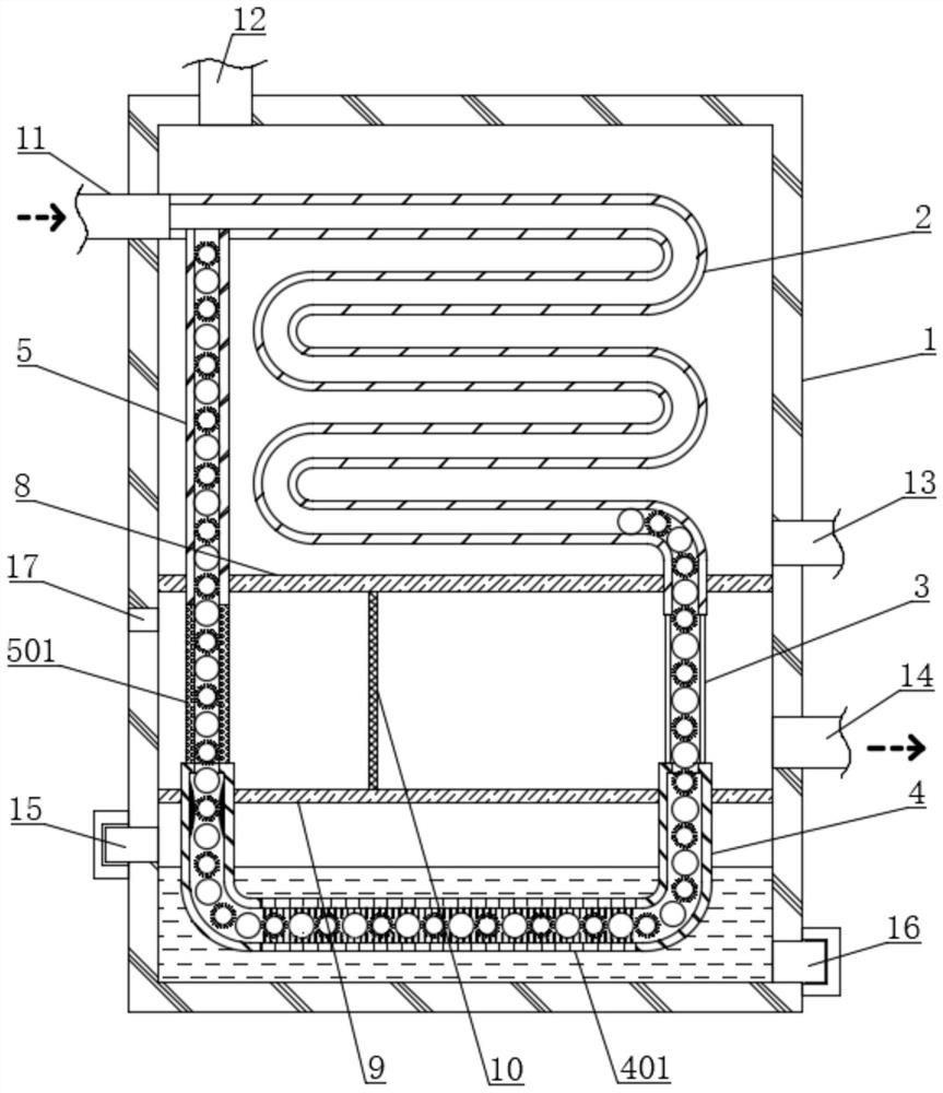
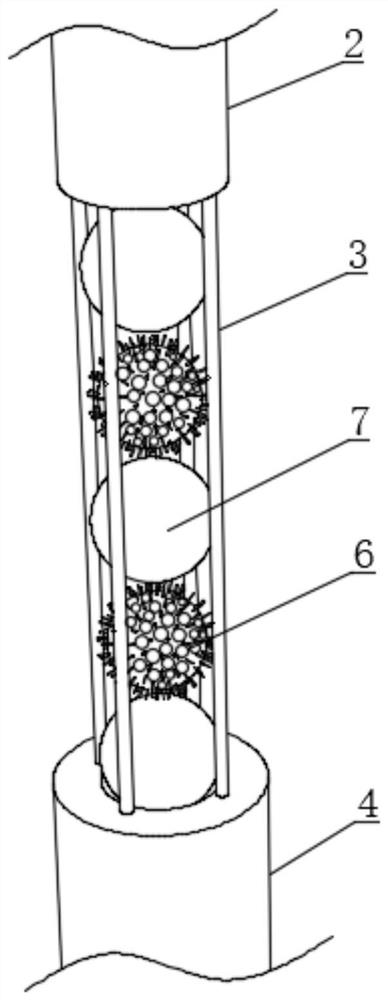
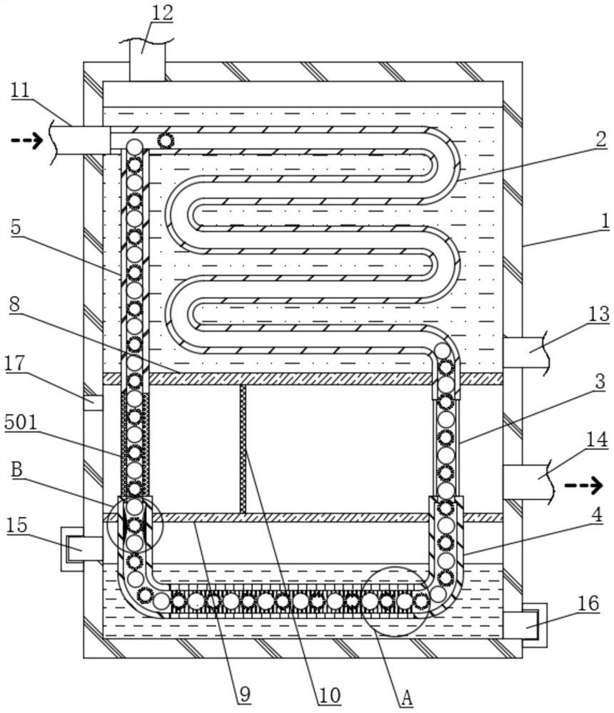
[0042] see figure 1 , a boiler flue gas waste heat recovery device, including a device shell 1, the inside of the device shell 1 is provided with a heat exchange tube 2, the upper end of the heat exchange tube 2 is fixedly connected with an air intake pipe 11, and the air intake pipe 11 runs through the side end of the device shell 1 And extend to the outside of the device shell 1, the lower side of the heat exchange tube 2 is provided with a U-shaped tube 4, please refer to figure 1 and figure 2 One end of the U-shaped tube 4 and the lower end of the heat exchange tube 2 are fixedly connected with a plurality of uniformly distributed guide vertical rods 3, and the other end of the U-shaped tube 4 is fixedly connected with a recovery tube 5, and the upper end of the recovery tube 5 is connected to the heat exchange tube 2. The outer end of the heat pipe 2 is fixedly connected, and the joint between the return pipe 5 and the heat exchange pipe 2 is located near the intake pip...


PUM


Abstract

The invention discloses a boiler flue gas waste heat recovery device and a recovery method, and belongs to the technical field of flue gas waste heat recovery. The boiler flue gas waste heat recoverydevice comprises a device shell, a heat exchange pipe is arranged in the device shell, and the upper end of the heat exchange pipe is fixedly connected with a gas inlet pipe. In the process of carrying out waste heat recovery on flue gas, main clearing balls and auxiliary clearing balls are pushed by flue gas flow, so that the main clearing balls and the auxiliary clearing balls cyclically and constantly roll in the heat exchange pipe in turns, the inner wall of the heat exchange pipe is constantly cleaned synchronously in the waste heat recovery process, and flue gas particulate matter attached to the inner wall of the heat exchange pipe is cleared away; and in the process that the main clearing balls and the auxiliary clearing balls complete clearing of one time on the heat exchange pipeand return to the gas inlet end of the heat exchange pipe, the processes of self cleaning, dewatering, drying and the like are sequentially achieved, then the main clearing balls and the auxiliary clearing balls enter the heat exchange pipe again to clean the heat exchange pipe, and therefore the clearing effect to the heat exchange pipe is further guaranteed.

Description

technical field [0001] The invention relates to the technical field of flue gas waste heat recovery, and more specifically, relates to a boiler flue gas waste heat recovery device and recovery method. Background technique [0002] Due to the shortage of energy sources, with the further development of energy-saving work. A variety of new, energy-saving and advanced furnace types are becoming more and more perfect, and the use of high-quality insulation materials such as new refractory fibers has significantly reduced the heat dissipation loss of the furnace. The advanced combustion device is used to strengthen the combustion, reduce the amount of incomplete combustion, and the air-fuel ratio tends to be reasonable. However, the technology of reducing heat loss from flue gas and recovering flue gas waste heat is still not progressing fast. In order to further improve the thermal efficiency of the kiln and achieve the goal of saving energy and reducing consumption, recovering ...

Claims


Application Information

Patent Timeline
Patent Type & Authority Applications(China)
IPC IPC(8): F28D7/08F28G1/02F28G1/12F28G15/00F26B5/14
CPCF26B5/14F28D7/082F28G1/02F28G1/12F28G15/00Y02P70/10
Inventor 张献安
Owner 四川陆亨能源科技有限公司
Why Eureka
Try Eureka