Method for detecting the load of items to be washed, and dishwasher machine

a technology for washing items and washing machines, which is applied in the direction of washing/rinsing machines, cleaning processes and apparatus, and household cleaners. it can solve the problems of insufficient design, inaccurate load recognition, and items to be washed optionally positioned therein the crockery bask

Active Publication Date: 2010-11-25
BSH BOSCH & SIEMENS HAUSGERAETE GMBH
View PDF5 Cites 17 Cited by
  • Summary
  • Abstract
  • Description
  • Claims
  • Application Information

AI Technical Summary

Benefits of technology

[0013]In the method according to the invention for determining the type and / or quantity of items to be washed in a dishwasher machine, an image detection system is used which measures distances in a non-contact manner by means of the speed of light in order to obtain a three-dimensional image of the washing chamber. The particular advantage of this procedure is that the evaluation of a three-dimensional image which in particular takes into account the distance of the respective items to be washed from the image detection system can give a more reliable image of the load of items to be washed than is the case in the procedure known from the prior art, wherein only one two-dimensional image of the load of items to be washed can be generated.
[0015]The photosensitive pixel elements preferably comprise so-called pixel elements known from the prior art, e.g. DE 197 04 496 C2. Such a pixel element is capable of measuring distances in a non-contact manner by means of the speed of light in order to determine three-dimensional images therefrom. In this case, the surroundings are illuminated with ultrafast pulsed electromagnetic waves. These waves are used as a time reference and are invisible to the human eye. The photosensitive pixel elements comprise a photodiode with two outputs which alternately read out the reflected light at a very high clock rate and thus calculate information on the transit time of the electromagnetic waves. The different distances of the “illuminated” items to be washed can be concluded from the different transition times, An image detection system having such a structure can be integrated in a single chip and can be produced cost-effectively using commonly used CMOS semiconductor production processes. A considerable economic benefit can be achieved by this means compared with the camera systems known from the prior art. Compared with an image detection system based on a mini camera, high-powered illumination can be dispensed with so that the energy consumption can advantageously be reduced.
[0017]It is advantageous to assign one or more image recognitions system(s) to at least each receptacle for items to be washed which separately determines the load of items to be washed in each receptacle.
[0018]In a further appropriate embodiment, it is provided that an image detection system should be assigned to the filter for collecting contamination residue. When contamination residue is detected in the filter, a signal which is identifiable for the user of the dishwasher machine, for example, can be emitted to indicate cleaning of the filter. This ensures that the cleaning performance of the dishwasher machine is the best possible in every washing process.
[0021]According to another appropriate embodiment, the image detection of the loading of the washing chamber according to type and quantity can be made before beginning a washing program started by a user. After the load of the respective crockery baskets has been determined by the image detection system, the dishwashing agent and the washing liquid can be metered and their degree of heating can be determined depending on said load. If the upper and lower dishwashing baskets are differently loaded, a larger quantity of dishwashing liquid could be supplied to the more heavily loaded dishwashing basket. The precise knowledge of the load of items to be washed allows a respective washing program to be controlled as required.
[0023]The items to be washed can be detected during introduction into the washing chamber or during loading of the receptacles for said items to be washed. For this purpose, the image detection system could be arranged on the side of the appliance door facing the washing chamber or on the upper side of the washing chamber. According to another embodiment, the image detection of the washing chamber is made when the items to be washed are placed in the receptacles. This can take place, for example, after the door is closed each time. This makes it possible to start the dishwasher machine automatically. The automatic start need not necessarily take place when all the storage possibilities provided for this purpose are occupied with items to be washed but can also take place depending on the items to be washed detected by the image detection system. Thus, for example, a largely complete load could be defined as the starting criterion, for example, when items to be washed predominantly made of glass are detected whereas a smaller number of pots or pans could result in an automatic start in the event of a smaller load. In other words, the automatic start and the choice of washing program can be made dependent on which type of items are to be cleaned in the dishwasher machine and optionally, on the degree of contamination of the respective items to be washed which can also be determined by the image detection system.

Problems solved by technology

A disadvantage of this arrangement can be seen in that crockery parts located in the transmission beam of the signal emitter reflect and deflect the electromagnetic waves or acoustic waves emitted by the transmitters with the result that items to be washed optionally positioned therebehind in the crockery basket are not precisely detected despite the diagonal alignment of the transmitter and receiver.
The load recognition is therefore inaccurate and additionally provides only a two-dimensional image of the loading of the receptacle for the items to be washed.
A disadvantage of this arrangement is that camera systems of the specified type are expensive and are not designed per se for use in water-carrying appliances.
In addition, the proposed system can only produce a two-dimensional image of the items to be washed positioned in the washing chamber.

Method used


Image

  • Method for detecting the load of items to be washed, and dishwasher machine
  • Method for detecting the load of items to be washed, and dishwasher machine

Examples


Embodiment Construction

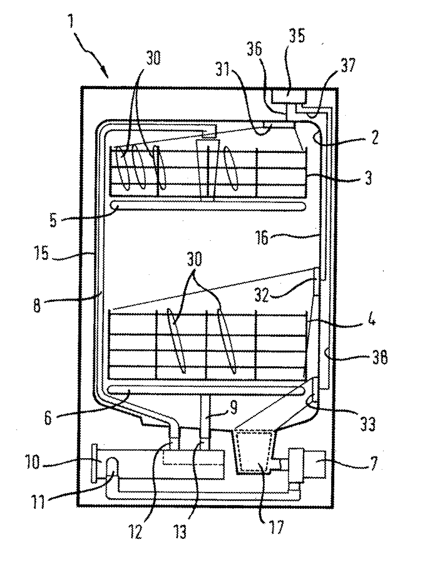
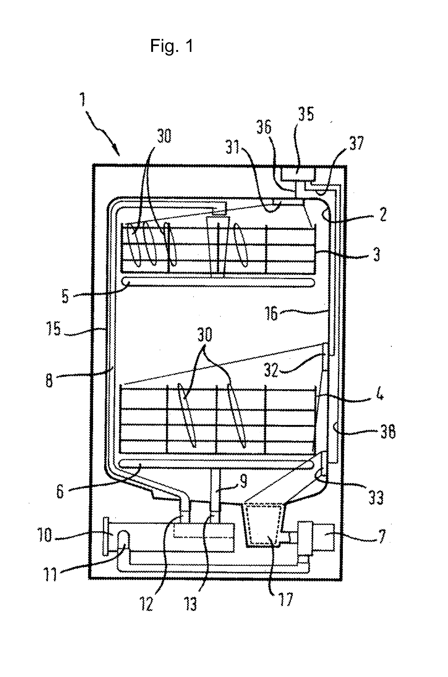
[0028]The dishwasher machine 1 according to the invention has a washing container 2 in which crockery 30 to be cleaned, for example in the form of plates, pots, cutlery etc. is usually loaded in crockery baskets 3, 4 forming receptacles for the items to be washed. Two spray devices 5, 6 are arranged in the washing container 2 to act upon the items 30 to be cleaned with washing liquid. The washing liquid is conveyed to the spray devices 5, 6 by means of a circulating pump 7 in liquid supply lines 8, 9.

[0029]Washing liquid conveyed into the dishwasher machine 1 is usually heated in a partial program section of a washing program for which a continuous flow heater 10 is used. The conveyed washing liquid is guided from the circulating pump 7 to an intake connection 11 of the continuous flow heater 10 and through said continuous flow heater 10. Said heater has at least two output connections 12, 13 from which the liquid is fed to the respective spray devices 5, 6 via liquid supply lines 8...


PUM


Abstract

A method for determining at least one of the type and the quantity of items to be washed in a dishwasher machine is provided for use with a dishwashing machine having a washing chamber in which the items are placed in receptacles for subsequent washing of the items during a dishwashing program with the respective disposition of the items in the receptacles constituting the load of the receptacles in the washing chamber of the dishwasher machine. The method includes detecting the load of the receptacles by an image detection system that measures distances in a non-contact manner by means of the speed of light such that the measured distances can be evaluated to obtain a three-dimensional image of the washing chamber.

Description

CROSS REFERENCE TO RELATED APPLICATIONS[0001]This application is a divisional under 35 U.S.C. §121 of U.S. application Ser. No. 11 / 628,520, filed Nov. 29, 2006, which is a U.S. national stage application, under 35 U.S.C. §371, of International Application No. PCT / EP2005 / 053510, filed Jul. 20, 2005, which designated the United States; this application also claims the benefit under 35 U.S.C. §119 of German Patent Application No. 10 2004 035 847.8, filed Jul. 23, 2004.BACKGROUND OF THE INVENTION[0002]The invention relates to a method for detecting the load of items to be washed in a dishwasher machine in which the items to be washed are placed in receptacles in the washing chamber of the device, wherein the loading of the receptacles for the items to be washed is detected by an image detection system. The invention further relates to a dishwasher for carrying out the method.[0003]Program-controlled dishwashing machines, in particular used in the household, can be operated in an energy-...

Claims


Application Information

Patent Timeline
Patent Type & Authority Applications(United States)
IPC IPC(8): B08B7/04
CPCA47L15/4295A47L2401/04A47L2401/30A47L2501/28A47L15/42A47L15/46
Inventor CLASSEN, EGBERTJERG, HELMUT
Owner BSH BOSCH & SIEMENS HAUSGERAETE GMBH
Why Eureka
Try Eureka