Supercharge Your Innovation With Domain-Expert AI Agents!

Worm shaft

A technology of worm shaft and worm gear, applied in the field of worm shaft

Inactive Publication Date: 2016-02-24
毅结特股份有限公司
View PDF11 Cites 0 Cited by
  • Summary
  • Abstract
  • Description
  • Claims
  • Application Information

AI Technical Summary

Problems solved by technology

[0008] The disadvantage of the system described above is that the axial extension of these worm shafts is specially designed for certain types of drive

Method used


Image

  • Worm shaft
  • Worm shaft
  • Worm shaft

Examples


Embodiment Construction

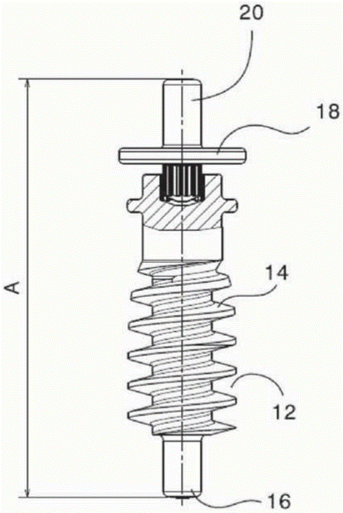
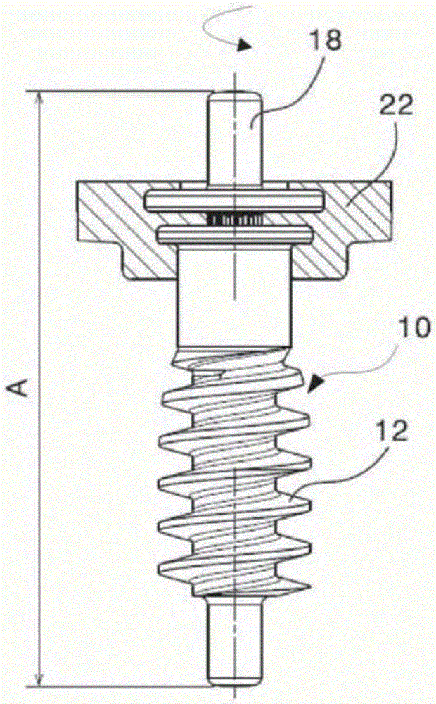
[0028] figure 1 is a schematic view of a first part and a second part of a worm shaft 10 according to the invention. The first part 12 includes threads 14 . A bearing pin 16 is provided at the end of the first worm shaft. The end of the worm shaft facing away from the first part has a second part 18 ; the second part is provided with a bearing pin 20 . The first part 12 and the second part 18 are arranged such that the end of the first bearing pin 16 and the end of the second bearing pin 20 are spaced apart from each other by a predetermined axial extension A length of the worm shaft. Such as figure 2 As shown in more detail in , the first part 12 and the second part 18 are thus tightly connected to each other in relative positions, and finally determine the axial extension A length of the worm shaft 10 .

[0029] In this way, the first part 12 and the second part 18 can be produced for a plurality of different axial extension A lengths without any adaptation; this is bec...


PUM


Abstract

The invention relates to a worm shaft (10), comprising a first component (12), which bears a first screw flight (14) and which has a first worm shaft end, and a second component (18), which has a second worm shaft end, wherein the axial extension (A) of the worm shaft (10) is defined by the spacing of the first worm shaft end to the second worm shaft end, wherein the axial extension (A) is fixed by connecting the first and the second components (12, 18) at a predefined spacing by means of an attachment member. The invention is characterised in that the axial extension (A) of the worm shaft (10) is set by the axial extension (A) of the attachment member.

Description

technical field [0001] The invention relates to a worm shaft as defined in the preamble of claim 1 and to a process for the manufacture of a worm shaft as defined in claim 7 . Background technique [0002] US 2007 / 0295134 A1 discloses a worm shaft for driving a mirror adjustment device. The worm shaft includes a shank having a first end and a second end. Wherein, the rod is used for accommodating the first part provided with threads; the first part slides into the rod through its first end, and is locked in the rod by the splint so that it cannot rotate. The worm shaft further has a second end, and the first part and the second part are connected to each other by a connecting element and are spaced apart from each other at a predetermined distance. [0003] EP1264735A1 also discloses a reflector adjustment device that uses a worm shaft to drive the reflector. Wherein, the worm shaft includes a spur gear and a part including threads; wherein, the worm shaft is mounted on t...

Claims


Application Information

Patent Timeline
IPC IPC(8): F16H55/22F16H55/06
CPCF16H55/06F16H55/22F16H2055/065
Inventor 安德烈亚斯·肯德威尔弗里德·宾泽
Owner 毅结特股份有限公司
Features
  • R&D
  • Intellectual Property
  • Life Sciences
  • Materials
  • Tech Scout
  • Unparalleled Data Quality
  • Higher Quality Content
  • 60% Fewer Hallucinations
Learn More