
Quick-fit hydraulic or hydrodynamic coupling for pressurised fluids

A technology for pressurizing fluids, couplers, applied in connections with fluid cut-off devices, valve operation/release devices, couplings, etc., to solve problems such as unavoidable risks

Active Publication Date: 2016-03-02
ALFAGOMMA
View PDF13 Cites 4 Cited by
  • Summary
  • Abstract
  • Description
  • Claims
  • Application Information

AI Technical Summary

Problems solved by technology

[0006] However, the operation is not exempt from risk due to concerns for the safety of the operators and it generates fluid waste which in turn must be recycled and disposed of
[0007] This operation also entails the risk of air being trapped in the fluid

Method used


Image

  • Quick-fit hydraulic or hydrodynamic coupling for pressurised fluids
  • Quick-fit hydraulic or hydrodynamic coupling for pressurised fluids
  • Quick-fit hydraulic or hydrodynamic coupling for pressurised fluids

Examples


Embodiment Construction

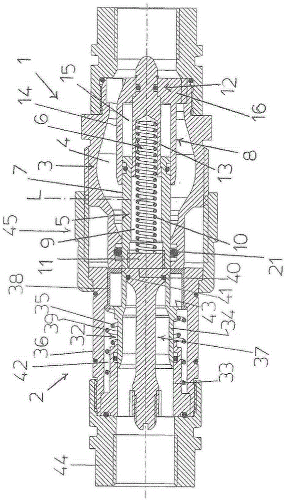
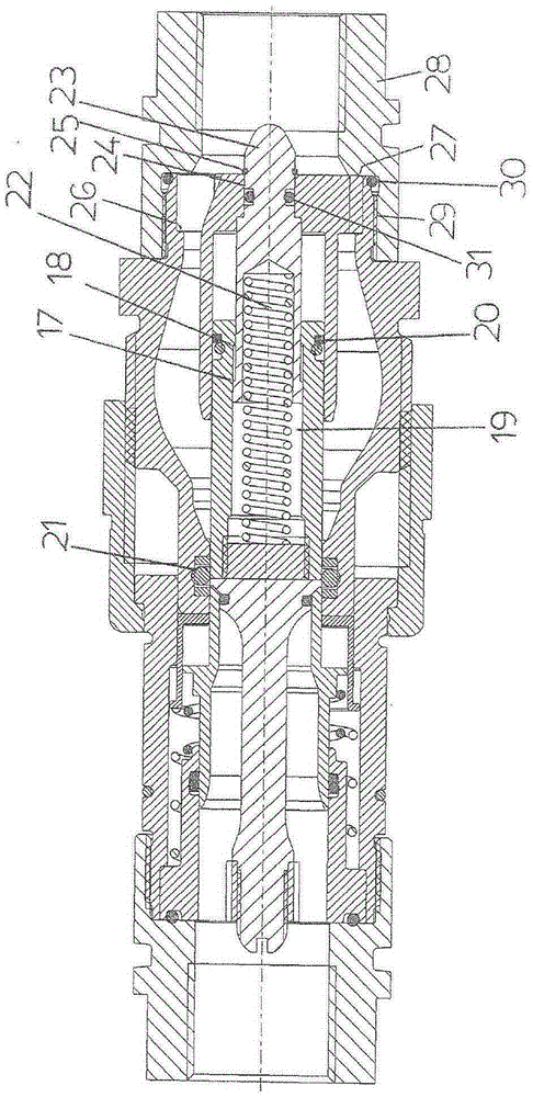
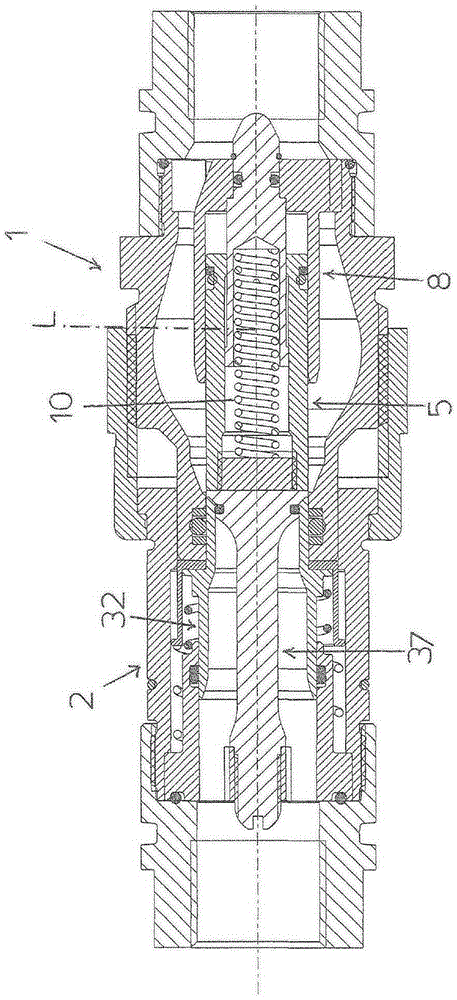
[0023] Referring to the figures cited above, there is shown a male quick-fit hydraulic or hydrodynamic coupler 1 and a female quick-fit hydraulic or hydrodynamic coupler 2 .

[0024] Male coupling 1 comprises: a valve body 3 extending along a longitudinal axis L and having a cavity 4 extending axially over the entire length of the valve body; and a shutter rod 5 coaxial with axis L Positioned in the cavity 6 and capable of opening the axial passage of the fluid through the cavity 4 opposite to and by means of the action of at least one elastic element 6 with respect to the valve body 3 along the axis L and a position for closing the axial passage of the fluid through the cavity 4.

[0025] In the position for closing the passage, the head end of the rod 5 and the head end of the valve body 3 are in hydraulic-tight contact along the periphery via the seal 21 .

[0026] In the position where the passage is opened by the effect of the relative movement between the rod 5 and the ...


PUM


Abstract

The quick-fit coupling (1) for pressurised fluid comprises a valve body (3) extending along a longitudinal axis (L) and having an axial cavity (4) wherein a shutter stem (5) is axially movable with respect to the valve body in contrast to and by action of at least one elastic element (6) between a position for opening and a position for closing an axial passage of fluid through said cavity (4), the stem (5) being configured so as to be subjected by the fluid present in the cavity (4) to a resultant force having a substantially null component at least in an axial direction.

Description

technical field [0001] The present invention relates to a quick-fit hydraulic or hydrodynamic coupling for pressurized fluid that can be used in agricultural and industrial applications. More specifically, the present invention relates to a quick-fit coupling comprising a valve body having an axial cavity, the shutter rod being extended and pressurized so as to be applied in the axial direction for opening fluid passing through said cavity. Relative movement between the position of the passage and the position of the axial passage for closing fluid through the cavity with respect to the valve body. Background technique [0002] The quick-fit coupler can be male or female respectively, and it can be engaged with the female coupler or the male coupler respectively, and its reciprocating motion locking is usually realized by the ring nut with the female coupler of. [0003] In the disconnected state, the coupler normally has a shutter in a position for closing the passage, wh...

Claims


Application Information

Patent Timeline
IPC IPC(8): F16L37/34
CPCF16L37/56F16L37/18F16L37/34F16K31/12F16L19/0206F16L21/08F16L29/007
Inventor E·吉纳索S·马佐里R·铎艾
Owner ALFAGOMMA
Learn More