Overlaying buckling sheet tooling

A tooling and buckle technology, which is applied in electromechanical devices, manufacturing motor generators, manufacturing stator/rotor bodies, etc., can solve problems such as low bending quality, low production efficiency, damage to buckle or stator punching, and achieve folding The effect of high bending quality, high alignment accuracy and fast bending speed

Active Publication Date: 2016-03-23
CHONGQING ELECTRIC MACHINE FEDERATION
View PDF7 Cites 9 Cited by
  • Summary
  • Abstract
  • Description
  • Claims
  • Application Information

AI Technical Summary

Problems solved by technology

[0004] The disadvantage of this punch lamination machine is that the stator punch needs to use a special punch lamination machine according to the diameter of the shaft hole (the centering shaft of the professional punch lamination machine matches the stator punch shaft hole) ), the versatility is not strong, and the cost is high; on the other hand, because the diameter of the centering shaft is slightly smaller than the diameter of the shaft hole of the stator, it is easy to shift when several stator punches are stacked (that is, the axes of the stator punches cannot be aligned) ;Finally, the manual bending of the buckle is used, the production efficiency is low, the bending quality is low, and the buckle or stator punching is easy to be damaged when the hammering force is too large, resulting in waste products

Method used


Image

  • Overlaying buckling sheet tooling
  • Overlaying buckling sheet tooling

Examples


Embodiment 1

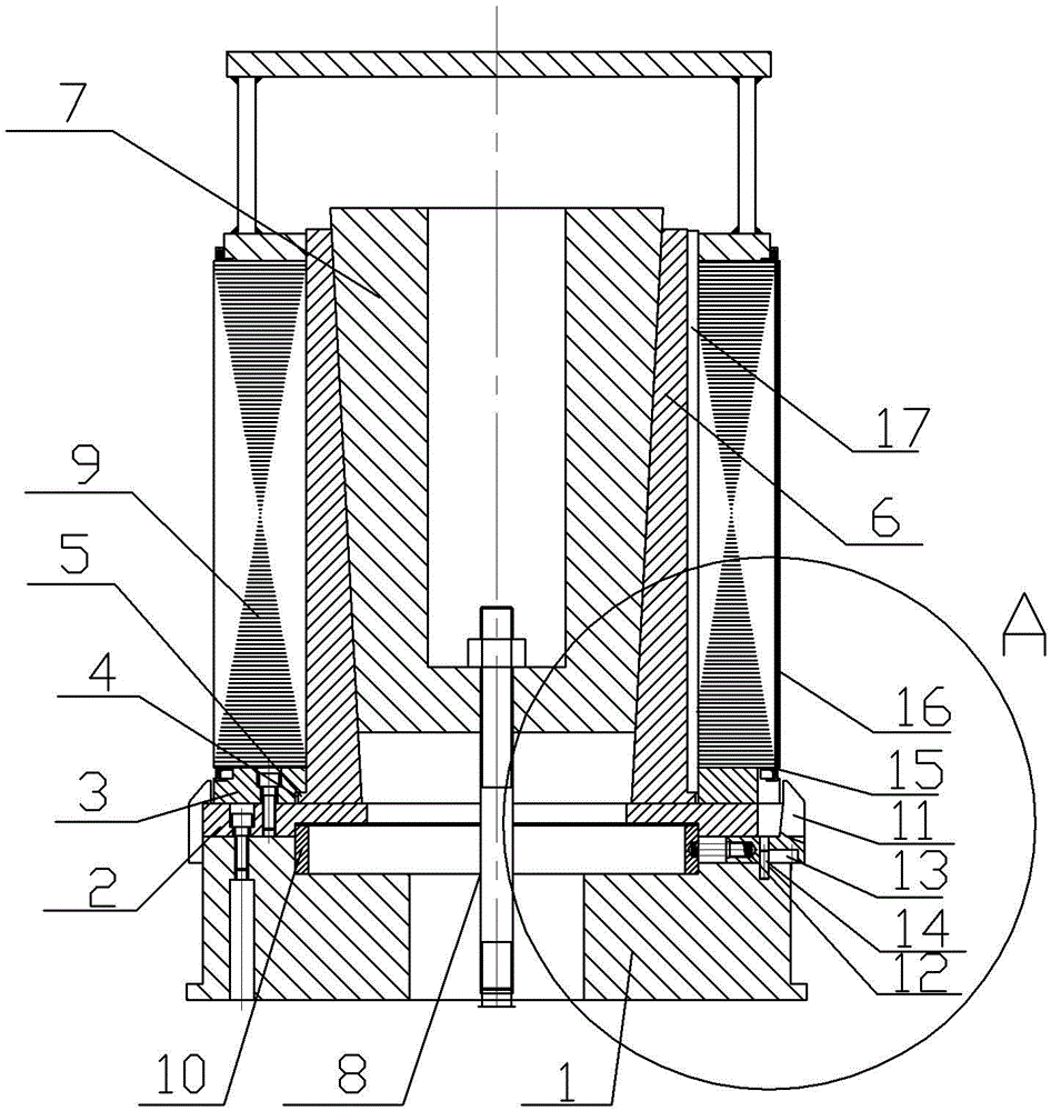
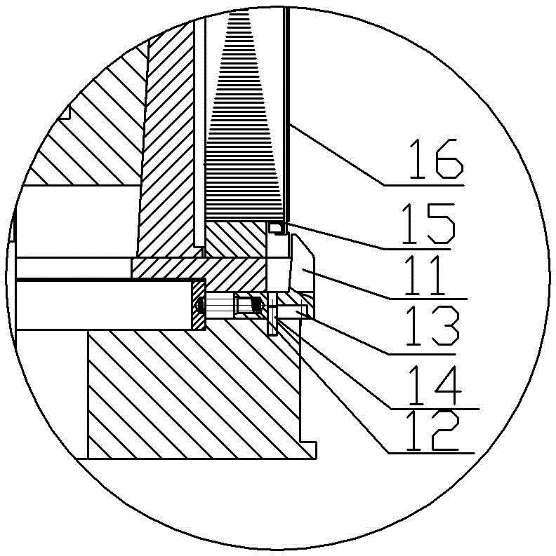
[0020] A stack of buckle tooling is basically attached figure 1 , figure 2 As shown: it includes a base 1 fixed on the sheet lamination machine by bolts. There is a shaft hole in the center of the base 1. The shaft hole is a stepped hole, and an inner retaining ring 10 is interference fit at the step of the stepped hole. The upper end surface of the base 1 is fixed with an annular backing plate 2 by hexagon socket head cap screws. A cylindrical core 6 is placed on the backing plate 2, and the core 6 is assembled from three independent core valves. There is a tapered hole in the core tire 6, and the diameter of the tapered hole decreases gradually from top to bottom. The tapered hole, the backing plate 2, and the stepped hole of the base 1 are concentric.

[0021] The surface of the backing plate 2 is fixed with a ring-shaped lower pressure ring 3 by hexagon socket head screws. The lower pressure ring 3 is located on the periphery of the core tire 6 and is concentric with th...

Embodiment 2

[0025] The difference from Embodiment 1 is that a linear drive motor is used to replace the telescopic cylinder, and the output shaft of the linear drive motor is connected to the lower end of the screw rod 8 through a flange.


PUM


Abstract

The invention belongs to the technical field of stator overlaying. The overlaying buckling sheet tooling comprises a base and a core tyre; an annular base plate is fixed on the surface of the base; the core tyre is placed on the base plate; an axle hole is formed in the center of the base; the core tyre is formed by multiple detachable split cores in a spliced manner; an inner hole is formed in the core tyre; the inner hole is a taper hole that is gradually reduced from upper to lower; an expansion tyre is glidingly matched in the taper hole; an annular lower pressing ring is fixed on the surface of the base plate; the lower pressing ring is positioned on the periphery of the core tyre; a matched limiting structure is arranged on the surface, opposite to the split cores, of the inner circle of the lower pressing ring; the expansion tyre, the core tyre and the lower pressing ring are all concentric with the axial ole of the base; two opposite sliding grooves are formed in the base in a radial direction of the axle hole; clamping jaws are glidingly matched in the sliding grooves; the inserting ends, in the sliding grooves, of the clamping jaws are connected with the end parts of the sliding grooves through springs; and stop pins fixed with the base are arranged on the clamping jaws. The scheme of the overlaying buckling sheet tooling is high in universality, high in alignment precision and good in bending quality of the buckling sheet.

Description

technical field [0001] The invention belongs to the technical field of stator lamination. Background technique [0002] The stator core is an important part of the motor. Its main function is: when the motor is in the power generation state, the magnetic field lines generated by the rotor form a closed loop, and the electromagnetic wires wound in the slots of the stator core cut the magnetic field lines generated by the rotor. , so as to generate an induced current in the electromagnetic wire; when the motor is in the electric state, when the electromagnetic wire wound in the iron core slot is energized, the iron core slot is induced to attract and repel the magnetic pole and the rotor magnetic pole, pushing and pulling the rotor to rotate , so that the rotor shaft outputs power outward. [0003] The existing stator core is formed by stacking stator punches (usually silicon steel sheets). The existing punch lamination machine includes a centering shaft and an embedded rod. ...

Claims


Application Information

Patent Timeline
Patent Type & Authority Applications(China)
IPC IPC(8): H02K15/02
CPCH02K15/026
Inventor 张兴阁
Owner CHONGQING ELECTRIC MACHINE FEDERATION
Why Eureka
Try Eureka