
Torque output tool

A torque output and tool technology, applied in the field of torque output tools, can solve the problems of affecting the service life of electric tools and reducing work efficiency

Inactive Publication Date: 2017-04-19
NANJING CHERVON IND
View PDF6 Cites 1 Cited by
  • Summary
  • Abstract
  • Description
  • Claims
  • Application Information

AI Technical Summary

Problems solved by technology

When the staff needs to switch between drilling and screwing continuously, the electric tools need to be replaced frequently, which not only reduces the work efficiency, but also seriously affects the service life of the electric tools

Method used


Image

  • Torque output tool
  • Torque output tool
  • Torque output tool

Examples


Embodiment Construction

[0022] The present invention will be specifically introduced below in conjunction with the accompanying drawings and specific embodiments.

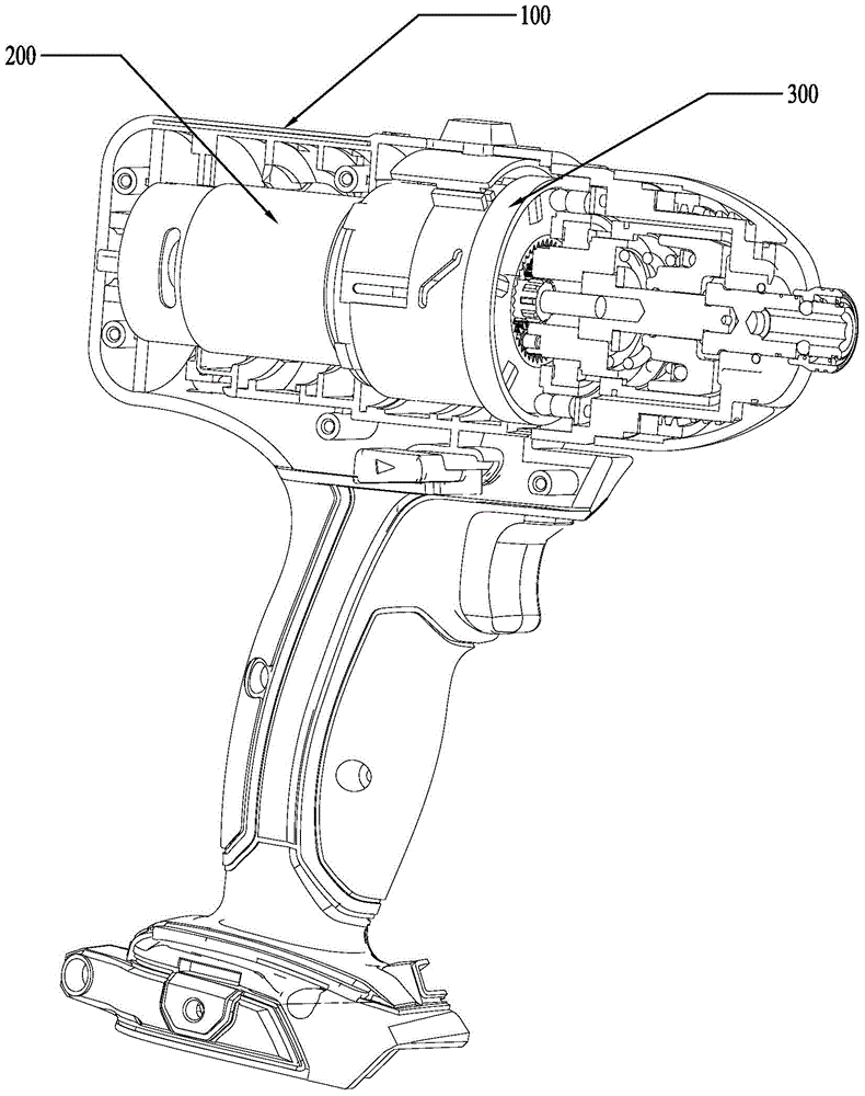
[0023] The invention provides a torque output tool. figure 1 Shown is a schematic structural view of the torque output tool of the present invention. Please refer to figure 1 , the torque output tool of the present invention includes a casing 100, a motor 200, and a transmission assembly 300, wherein the casing 100 forms a housing space (not shown) for accommodating the motor 200 and the transmission assembly 300, and the motor 200 is arranged in the storage space formed by the casing 100 The transmission assembly 300 is driven by the motor 200 and can transmit and output the power generated by the motor 200 .

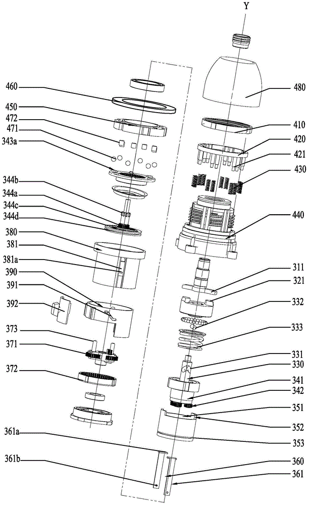
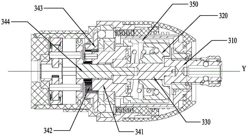
[0024] figure 2 shown as figure 1 Schematic diagram of the explosion of the middle part of the structure; image 3 shown as figure 1 Schematic cross-sectional view of the middle part structure, at this moment, the first cen...


PUM


Abstract

The invention discloses a torsion force output tool comprising a housing, a motor, and a transmission assembly driven by the motor; the transmission assembly comprises an output shaft, a hammer body, a main shaft, and a first planetary gear train; the first planetary gear train comprises a first planetary gear rack arranged in the housing in a rotary manner and always synchronically rotating with the main shaft, a first level planetary gear connected with the first planetary gear rack in a rotary manner, a first ring gear arranged outside and engaged with the first level planetary gear, and a first central wheel capable of sliding to a first position and a second position in a first axial direction; the transmission assembly also comprises a locking piece making synchronical sliding with the first central wheel; when the first central wheel is in the first position, the locking piece only lock the relative peripheral positions of the output shaft and the first planetary gear rack; when the first central wheel is in the second position, the locking piece only forms peripheral cooperation with the first planetary gear rack. The torsion force output tool can use simple operation to realize a drill mode and an impact mode.

Description

technical field [0001] The invention relates to a torque output tool, in particular to a torque output tool with multiple modes. Background technique [0002] In the process of using the existing electric tools, on the one hand, people hope that the electric tools can work continuously, so that the electric tools can be used as electric drills, and on the other hand, they hope that the electric tools can work intermittently, so that the electric tools can be used as tightening screwdrivers . When the staff needs to constantly switch between drilling and screwing, the electric tool needs to be replaced frequently, which not only reduces the work efficiency, but also seriously affects the service life of the electric tool. For this reason, people are badly in need of a kind of only by simple switching operation and can make same power tool both as electric drill and can be used as tightening screwdriver. Contents of the invention [0003] In order to solve the deficiencies...

Claims


Application Information

Patent Timeline
Patent Type & Authority Patents(China)
IPC IPC(8): B25B21/02B23B45/02B23B45/16
Inventor 陈翠华
Owner NANJING CHERVON IND
Learn More