Robot system with visual servo and detection functions

A robot system and visual servo technology, applied in the field of robot systems, can solve the problems of low precision requirements of robot models, difficult to achieve integration, occupying production time, etc., and achieve the effect of improving motion control efficiency, convenient operation and simple structure

Active Publication Date: 2013-11-27
NORTHWESTERN POLYTECHNICAL UNIV
View PDF6 Cites 62 Cited by
  • Summary
  • Abstract
  • Description
  • Claims
  • Application Information

AI Technical Summary

Problems solved by technology

The advantage of this method is that the accuracy of the robot model is low, and the robot’s tool coordinate system does not need to be calibrated, and the theoretical model of the robot can be used; but its disadvantages are: the online teaching and programming process of the robot is cumbersome, the operation process is complicated, and the efficiency is low. , easy to fatigue, the accuracy depends entirely on the visual experience of the instructor, the accuracy is low, taking up valuable production time, and making the robot system a relative unit, it is difficult to achieve integration with other systems or production processes, and cannot meet today's small batches , Multi-variety flexible production needs
[0005] Invention patent 200510108256.5 discloses a robot system with a visual sensor. The system measures the three-dimensional relative position / posture error between the robot and surrounding objects through the visual sensor for one or more robots, and corrects the pre-taught position / posture. , but it does not have the quality detection function
In the invention patent 201110026529.7, an "industrial robot control system and control method based on vision positioning" is described. Real-time detection function

Method used


Image

  • Robot system with visual servo and detection functions
  • Robot system with visual servo and detection functions
  • Robot system with visual servo and detection functions

Examples


Embodiment Construction

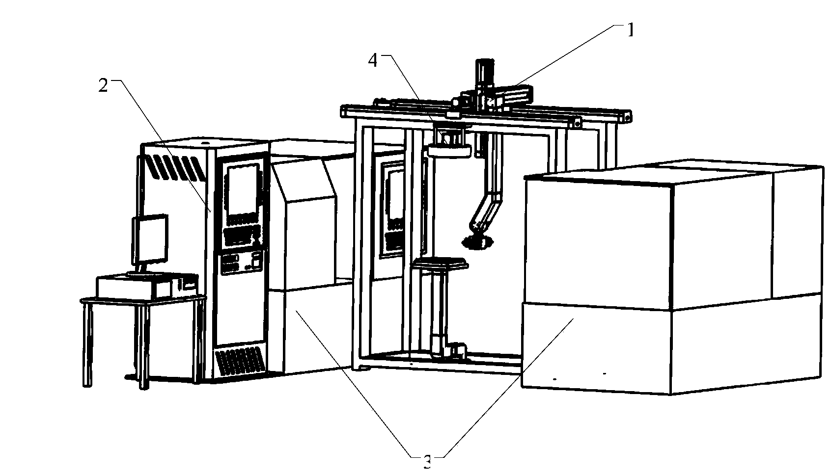
[0023] This embodiment is a robot system with visual servoing and detection functions.

[0024] refer to figure 1 , figure 2 The overall structure of the automatic loading and unloading three-coordinate robot unit and processing unit includes four parts, namely robot 1, robot visual servo control unit and communication network unit 2 connecting each module, CNC machine tool 3, image acquisition and image processing unit 4 . The robot 1 is installed between two CNC machine tools 3, and the robot 1 completes the task of loading and unloading the CNC machine tools 3; the robot visual servo control unit and the communication network unit 2 connecting each module are installed next to the CNC machine tools 3, and control the three Coordinate the movement of the robot 1, and the CNC machine tool 3 completes the processing of the workpiece; the image acquisition and image processing unit 4 is placed above the bracket 1 on the machine, and is used to photograph the robot’s work sit...


PUM


Abstract

The invention discloses a robot system with visual servo and detection functions. The robot system comprises a robot, an image acquisition and image processing unit, a robot vision servo control unit and a communication network unit for connecting all the modules, wherein data and signal transmission among all the units is realized by the communication network unit; the robot vision servo control unit sends or receives a control signal of the robot by the communication network unit, rapidly understands the surrounding and constructs a vision feedback control model at the same time, so as to realize vision identification and movement control functions of the robot. The movement control of the robot adopts a method of combining offline programming with robot vision servo control to carry out automatic control on the robot and a tail end executer, so that the movement control efficiency of the robot and the repeated positioning precision and flexibility of the robot are improved; the robot system has higher intelligence. Robot control has a non-contact quality detection function based on robot vision; the robot system is simple in structure and convenient to operate.

Description

technical field [0001] The invention belongs to the field of robots and automatic control, and in particular relates to a robot system with visual servo and detection functions. Background technique [0002] Due to the different operating tools of the end effector, the robot can be very conveniently used as various automation equipment to complete such as assembly, inspection, palletizing, loading and unloading, welding, handling, packaging, depalletizing, flaw detection, classification, spraying, labeling , coding, coding, target following and a series of work. Robots are especially suitable for flexible operations with multiple varieties and variable batches. They play a very important role in stably improving product quality, improving labor production efficiency, improving working conditions and rapid product replacement. The main task of robot control technology is to control the robot's movement position, posture and trajectory, operation sequence and action time in t...

Claims


Application Information

Patent Timeline
Patent Type & Authority Applications(China)
IPC IPC(8): B25J9/16B25J19/04
Inventor 秦现生王文杰洪杰牛军龙张培培沈东莹薛婷王润孝谭小群白晶
Owner NORTHWESTERN POLYTECHNICAL UNIV
Why Eureka
Try Eureka