Laser guide type ground glue-injection machine

A technology of laser guidance and glue injection machine, which is applied in the direction of construction and building construction, can solve the problems of not being able to meet the requirements of industrial production and construction assembly, not being able to meet the requirements of factory production and construction assembly, inconvenient replacement and reuse, etc., to achieve The effect of glue feeding and glue injection is convenient, the product quality is guaranteed, and the structure is simple

Active Publication Date: 2016-04-13
ZHEJIANG YASHA DECORATION
View PDF5 Cites 8 Cited by
  • Summary
  • Abstract
  • Description
  • Claims
  • Application Information

AI Technical Summary

Problems solved by technology

The traditional paving method is to use dry cement mortar, and then put the stone or tiles on the ground and vibrate it. Its advantages are mature technology, relatively fast construction speed, economical construction materials, and relatively easy The disadvantage of leveling is the reaction between cement and stone or tile sand, which is prone to some lesions and problems and takes a long time to construct. The surface layer and the structural layer are permanently bonded, which is not easy to replace and reuse, and it is easy to appear empty. Problems such as drumming, cracking, and falling off cannot meet the requirements of factory production and construction assembly
Another commonly used construction method is to use stone binder as a bonding material, which is suitable for direct bonding on concrete walls, concrete floors, asbestos cement boards, mortar bases, cement bases, and cement-based waterproof materials. The disadvantages of natural stone such as marble or granite are that the cost is relatively high and the construction period is relatively long, which cannot meet the requirements of industrial production and construction assembly.

Method used


Image

  • Laser guide type ground glue-injection machine

Examples


Embodiment Construction

[0021] The present invention will be further described below in conjunction with accompanying drawing of description, but protection scope of the present invention is not limited thereto:

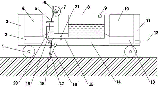
[0022] like figure 1 The laser-guided ground glue injection machine shown includes a frame and a roller 1 arranged at the bottom of the frame. There are 4 rollers 1, which are respectively arranged on the four corners of the frame. The two sides of the frame are respectively For the left side wall 3 and the right side wall 11, a base is set in the frame, and the base includes a left base 2, a middle base 14 and a right base 13, and the left base 2 is adjacent to the left side wall 3 of the frame, and the right base 13 Adjacent to the right side wall 11 of the frame, the left side wall 3 is provided with a motor 4, the right base 13 is provided with a controller 10, and the middle base 14 is provided with a glue injection device, which includes a glue storage room 8 and a glue injector, a g...


PUM


Abstract

The invention relates to a laser guide type ground glue-injection machine which comprises a rack and a rolling wheel. Bases are arranged in the rack and comprise a left base, a middle base and a right base. The left base is adjacent to the left side wall of the rack. The right base is adjacent to the right side wall of the rack. A motor is arranged on the left side wall of the rack. A controller is arranged on the right base. A glue-injection device is arranged in the middle of the middle base in a penetrating mode and comprises a glue storing chamber and a glue-injection device. A laser transmitter is arranged on the right side wall. A depth probing device is arranged at the bottom of the middle base and located at one side of a glue-injection needle head of the bottom of the glue-injection deice. The controller is connected with the motor, the laser transmitter and the depth probing device. The glue-injection machine is simple in structure, glue feeding and injecting are convenient, and controllability is good; after the finite glue-injection device is adopted for injecting glue on the ground, natural stones such as marble and granite can be directly bonded to the glue base plane, industrial production of construction is achieved, construction speed is greatly increased, economic cost is greatly saved, and the construction period is shortened.

Description

technical field [0001] The invention belongs to the technical field of a glue injection machine for architectural decoration, and more specifically relates to a laser-guided floor glue injection machine. technical background [0002] Stone and ceramic tiles are widely used in the laying of architectural decoration projects such as hotels, residences, office spaces, square floors, and residential balconies. The traditional paving method is to use dry cement mortar, and then put the stone or tiles on the ground and vibrate it. Its advantages are mature technology, relatively fast construction speed, economical construction materials, and relatively easy The disadvantage of leveling is the reaction between cement and stone or tile sand, which is prone to some lesions and problems and takes a long time to construct. The surface layer and the structural layer are permanently bonded, which is not easy to replace and reuse, and it is easy to appear empty. Problems such as drumming...

Claims


Application Information

Patent Timeline
Patent Type & Authority Applications(China)
IPC IPC(8): E04F21/24
CPCE04F21/24
Inventor 余广周东珊朱洋丽吕亮王骝尤陈刚龚婷王倩
Owner ZHEJIANG YASHA DECORATION
Why Eureka
Try Eureka