Method for labeling containers in a beverage bottling plant and a labeling station for a labeling machine in a beverage bottle labeling plant

a beverage bottling plant and labeling station technology, applied in the directions of labelling, transportation and packaging, packaging, etc., can solve the problems of displacement of labels on transfer drums, difficult to convert to different label lengths, and more expensive construction, so as to minimize the soiling of functional elements, maximize the effect of accuracy and save glu

Inactive Publication Date: 2015-11-03
KHS GMBH
View PDF15 Cites 5 Cited by
  • Summary
  • Abstract
  • Description
  • Claims
  • Application Information

AI Technical Summary

Benefits of technology

[0015]An object of the present application is to demonstrate a method which minimizes the aforementioned limitations and which, without the risk of soiling the labeling station used or its functional elements, can be used to apply glue with maximized accuracy when using a web or strip-shaped labeling material.SUMMARY
[0017]One feature of the present application is that the glue is applied onto the web or strip-shaped labeling material prior to the separation of the labels from this material. The glue is applied with at least one nozzle-type glue application head, and, in at least one possible embodiment of the present application using a glue application head which, at least during the application, is in contact with the labeling material. Using the respective glue application head, for example, very narrow strip-shaped glue applications, e.g. with a breadth of one millimeter to two millimeters, saving glue and with maximized accuracy, even when the labeling station or the labeling machine is high-output (high number of labeled containers per unit of time) can be achieved without any problem. The glue-applying functional element, namely the glue application head or at least one nozzle thereof, is covered by the labeling material at all times, virtually all times, or substantially all times during operation of the labeling station. This effectively minimizes any soiling of functional elements of this station with glue or glue components.
[0018]The glue application head used is, in at least one possible embodiment, designed so that it can apply glue intermittently, for example to produce narrow, strip-shaped glue applications, but continuous application of the glue is also possible, in the latter case in order to obtain labels which are provided, on their reverse side, with a glue application extending over the entire length of the label. Here, too, a feature of the present application resides in the fact that this glue application extending over the entire length of the label is effected with maximized accuracy and minimizes any soiling of functional elements of the labeling station.
[0020]If the glue is applied intermittently, by selectively turning on and off the glue application head, taking account of the breadth of the nozzle gap, the breadth of the glue application running in the form of a strip, perpendicular, virtually perpendicular, substantially perpendicular, or essentially perpendicular to the longitudinal extension of the labeling material, can be controlled and / or varied without any problem.

Problems solved by technology

These raised areas mean more expensive construction and make it difficult to convert to different label lengths.
One substantial limitation of some methods, however, is also the risk that when applying glue, the glue-applying functional elements touching the labels, i.e. glue rollers or glue application heads, which abut on the respective label during application of glue, may displace the labels on the transfer drum or the labels may even lose contact, wholly or partly, with this drum.
A further limitation of some methods is also that the glue-applying functional elements are covered by the respective label for part of the time, but not, for example, between two consecutive labels on the transfer drum, which results in a considerable soiling of the transfer drum by glue.
This is the case when glue rollers are used, but also when glue application heads are used and when using contactless application heads, where there is the risk of soiling, e.g. due to glue swirls, etc.
Soiling incidents lead to functional problems in the respective labeling machine and also mean that long stoppage times may occur for cleaning.
The use of glue rollers also has the limitation that the glue is exposed to the ambient air over a very large area, so that when hot glue is used, the components thereof volatilize and may precipitate on adjacent parts or functional elements of the labeling station.
Also, when there is volatilization of components of the hot glue, the quality of this glue is adversely affected.
Glue application heads which enable contactless application of the glue have the further limitation of a complicated and time-consuming adjustment of these application heads, not least due to the fact that the respectively desired glue application is achieved when there is an optimally accurate arrangement and orientation of the application heads, at the same time maintaining an exact, substantially exact, or essentially exact clearance between the respective application head and the labels.

Method used


Image

  • Method for labeling containers in a beverage bottling plant and a labeling station for a labeling machine in a beverage bottle labeling plant
  • Method for labeling containers in a beverage bottling plant and a labeling station for a labeling machine in a beverage bottle labeling plant
  • Method for labeling containers in a beverage bottling plant and a labeling station for a labeling machine in a beverage bottle labeling plant

Examples


Embodiment Construction

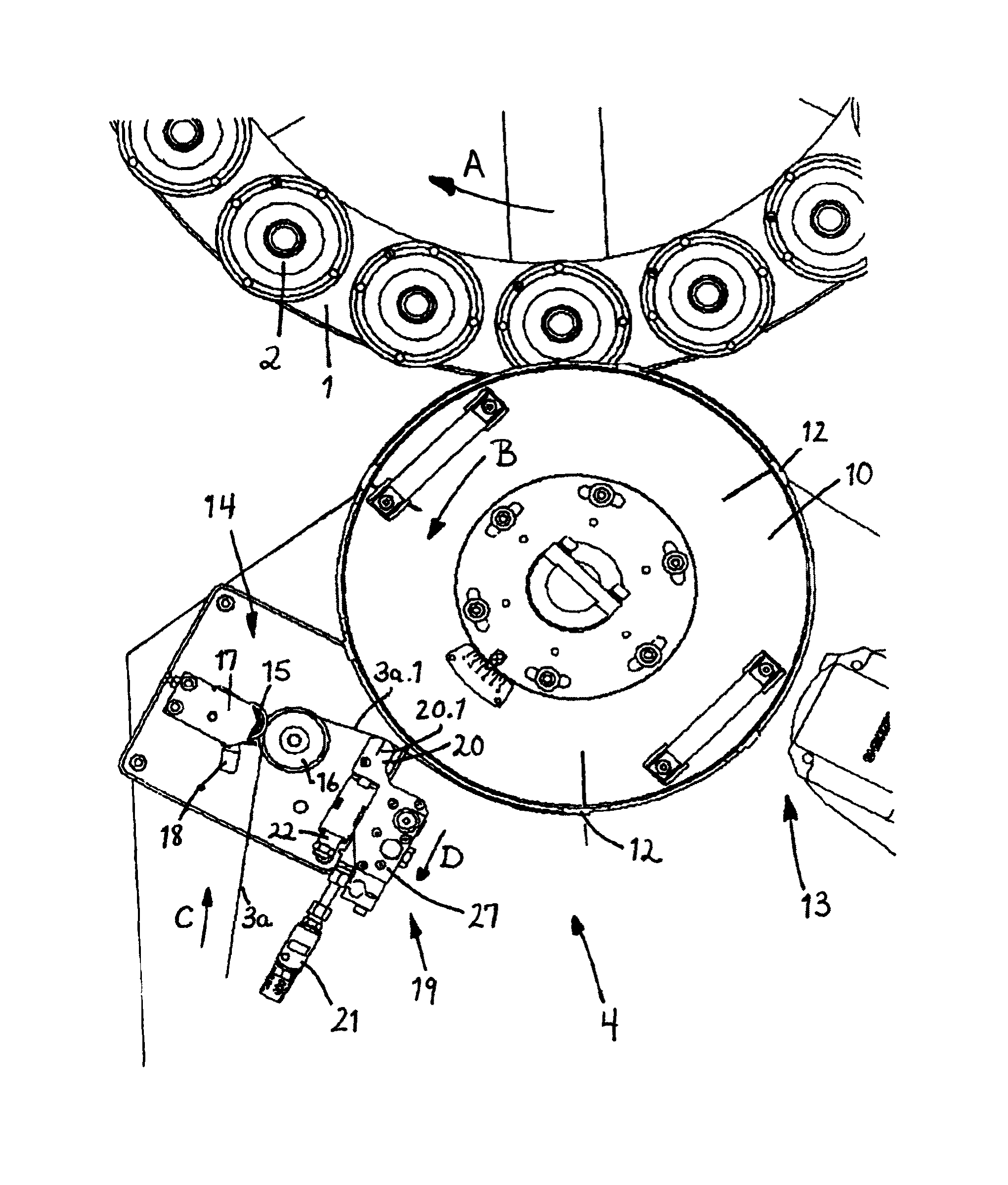
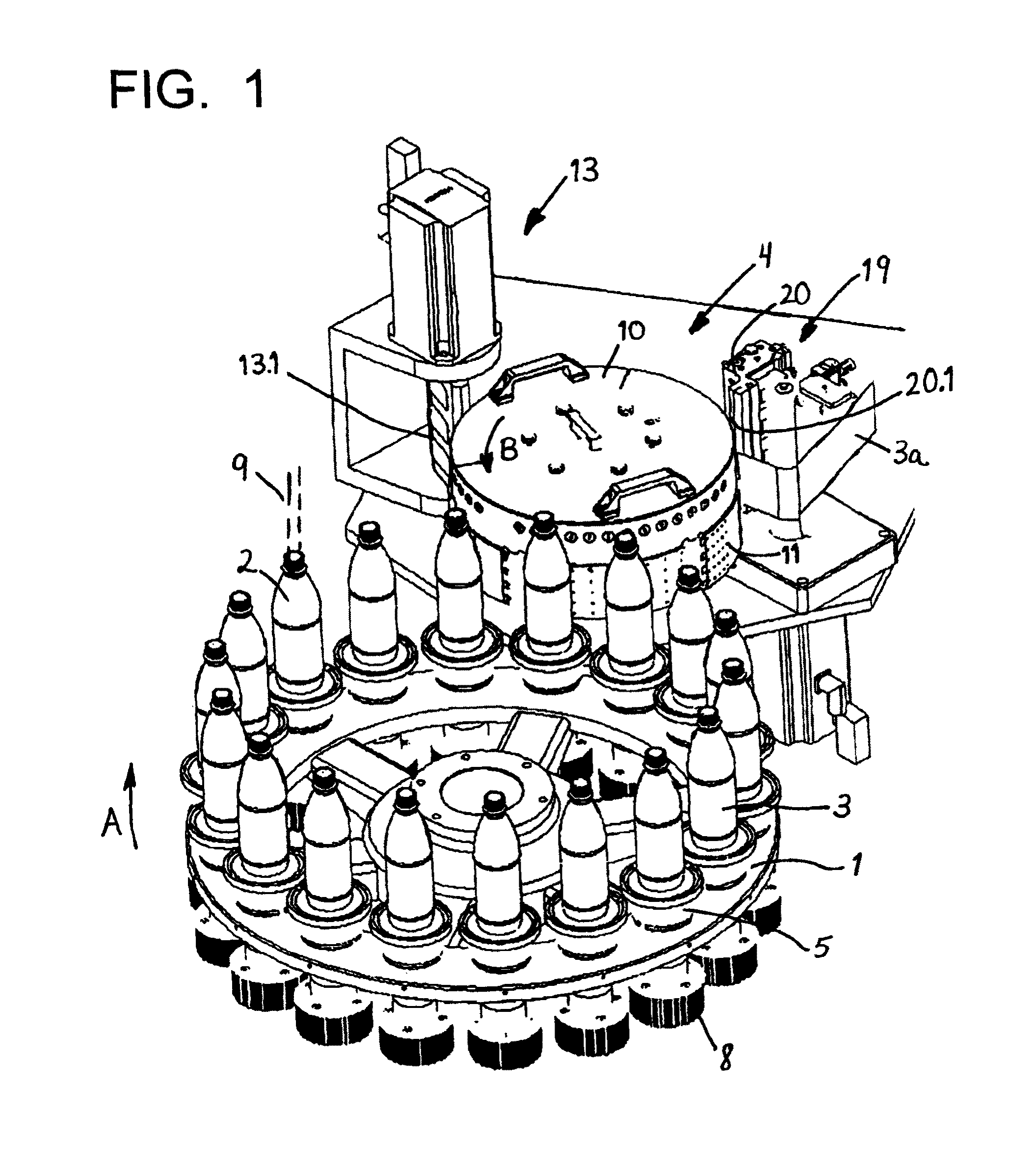
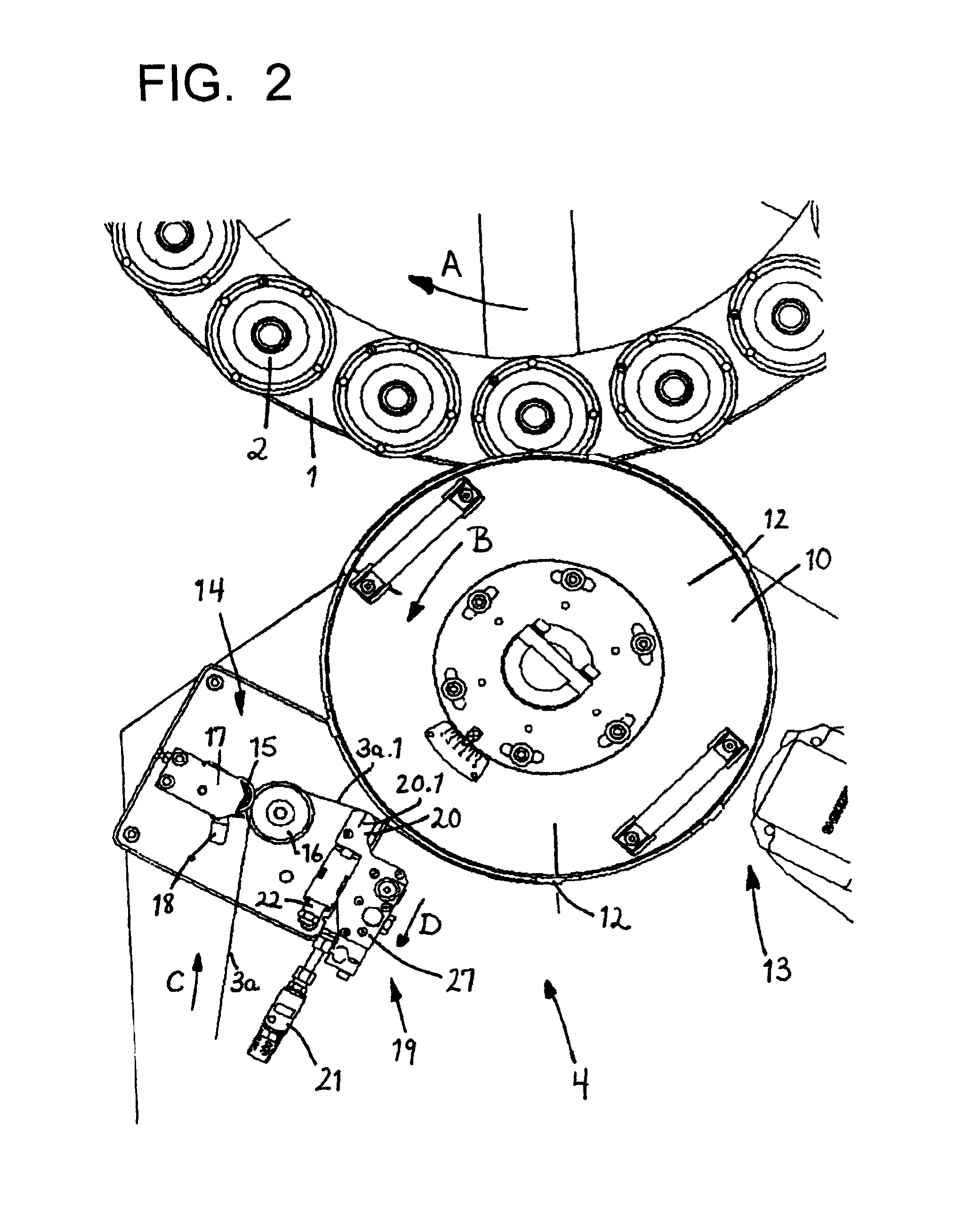
[0031]In the figures, 1 is the rotary-driven rotor of a rotary-type labeling machine rotating about a vertical, substantially vertical, or essentially vertical machine axis in the direction of the arrow A for labeling bottles 2 with an all-round label 3. The number 4 refers to a labeling station (labeling device) which is provided at the periphery of the rotor 1, not rotating with this latter, and is used to apply labels 3 onto the bottles 2 arranged standing upright with their bases on container carriers 5 (bottle pads) and moved by the rotor 1 past the labeling device 4.

[0032]For transfer to the bottles 2 and fixation thereon, the rectangular labels 3 in the labeling device 4 are provided during transfer to a bottle 2, on their leading narrow side and on the narrow side trailing during the transfer, with a strip-shaped application of glue 6 and 7 respectively, and this is on the reverse of the labels, so that with the leading glue application 6 each label 3 adheres to a bottle 2 t...


PUM

PropertyMeasurementUnit
pressureaaaaaaaaaa
angleaaaaaaaaaa
distanceaaaaaaaaaa

Abstract

A method for labeling containers in a beverage bottling plant and a labeling station for a labeling machine in a beverage bottle labeling plant. The abstract of the disclosure is submitted herewith as required by 37 C.F.R. §1.72(b). As stated in 37 C.F.R. §1.72(b): A brief abstract of the technical disclosure in the specification must commence on a separate sheet, preferably following the claims, under the heading “Abstract of the Disclosure.” The purpose of the abstract is to enable the Patent and Trademark Office and the public generally to determine quickly from a cursory inspection the nature and gist of the technical disclosure. The abstract shall not be used for interpreting the scope of the claims. Therefore, any statements made relating to the abstract are not intended to limit the claims in any manner and should not be interpreted as limiting the claims in any manner.

Description

CONTINUING APPLICATION DATA[0001]This application is a Continuation-In-Part application of International Patent Application No. PCT / EP2008 / 010094, filed on Nov. 27, 2008, which claims priority from Federal Republic of Germany Patent Application No. 10 2007 059 244.4, filed on Dec. 7, 2007. International Patent Application No. PCT / EP2008 / 010094 was pending as of the filing date of this application. The United States was an elected state in International Patent Application No. PCT / EP2008 / 010094.BACKGROUND[0002]1. Technical Field[0003]The present application relates to a method for labeling containers in a beverage bottling plant and a labeling station for a labeling machine in a beverage bottle labeling plant.[0004]2. Background Information[0005]Background information is for informational purposes only and does not necessarily admit that subsequently mentioned information and publications are prior art.[0006]The present application relates to a method and to a labeling station for lab...

Claims


Application Information

Patent Timeline
Patent Type & Authority Patents(United States)
IPC IPC(8): B65C3/12B65C9/18B65C9/22B32B38/04
CPCB65C9/1819B65C9/22B32B38/04Y10T156/1062Y10T156/1084Y10T156/1317Y10T156/1326Y10T156/1339Y10T156/1374Y10T156/1734
Inventor DECKERT, LUTZ
Owner KHS GMBH
Why Eureka
Try Eureka