Flow rate measuring device, and gas supply system employing it, method for specifying gas appliance

a flow rate and gas appliance technology, applied in the direction of fluid pressure measurement by mechanical elements, volume flow measuring devices, amplifier modifications to reduce noise influence, etc., can solve the problem of ambiguity in method, difficult fee setting, easy to understand and convenient for customers, etc. problem, to achieve the effect of accurate identification of gas appliances and facilitation of future maintenance of appliance functions

Active Publication Date: 2009-09-24
PANASONIC CORP
View PDF0 Cites 47 Cited by
  • Summary
  • Abstract
  • Description
  • Claims
  • Application Information

AI Technical Summary

Benefits of technology

[0012]Even when one gas appliance stops during operation of a plurality of gas appliances and it is difficult to identify the one gas appliance only based on the gas flow rate variation at the stop, the flow rate measuring device of the present invention can identify the one gas appliance. The flow rate measuri

Problems solved by technology

However, this method falls into ambiguity in identifying an appliance.
Therefore, it is difficult to perform fee setting, such as billing for a specific appliance, that is easier to understand and convenient for customers.
However, when a plurality of gas appliances are operated, it is difficult in some si

Method used


Image

  • Flow rate measuring device, and gas supply system employing it, method for specifying gas appliance
  • Flow rate measuring device, and gas supply system employing it, method for specifying gas appliance
  • Flow rate measuring device, and gas supply system employing it, method for specifying gas appliance

Examples


Embodiment Construction

[0036]An exemplary embodiment of the present invention is described hereinafter with reference to the accompanying drawings. However, the present invention is not limited to the following exemplary embodiment.

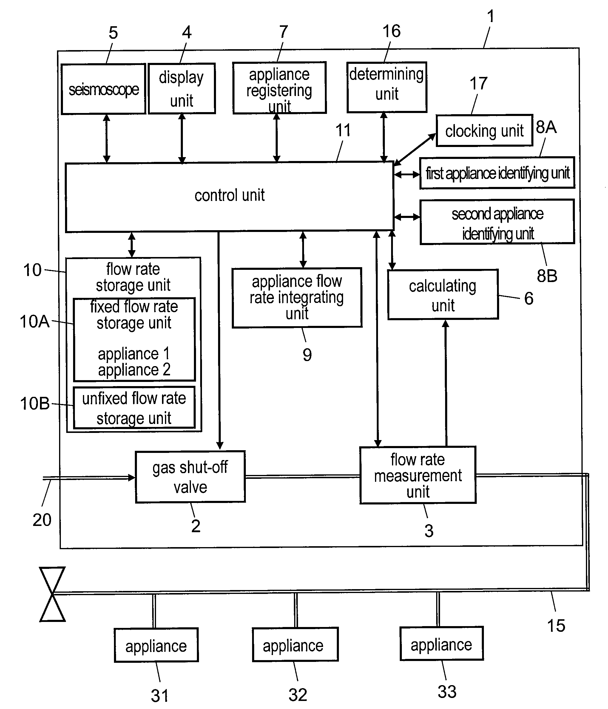
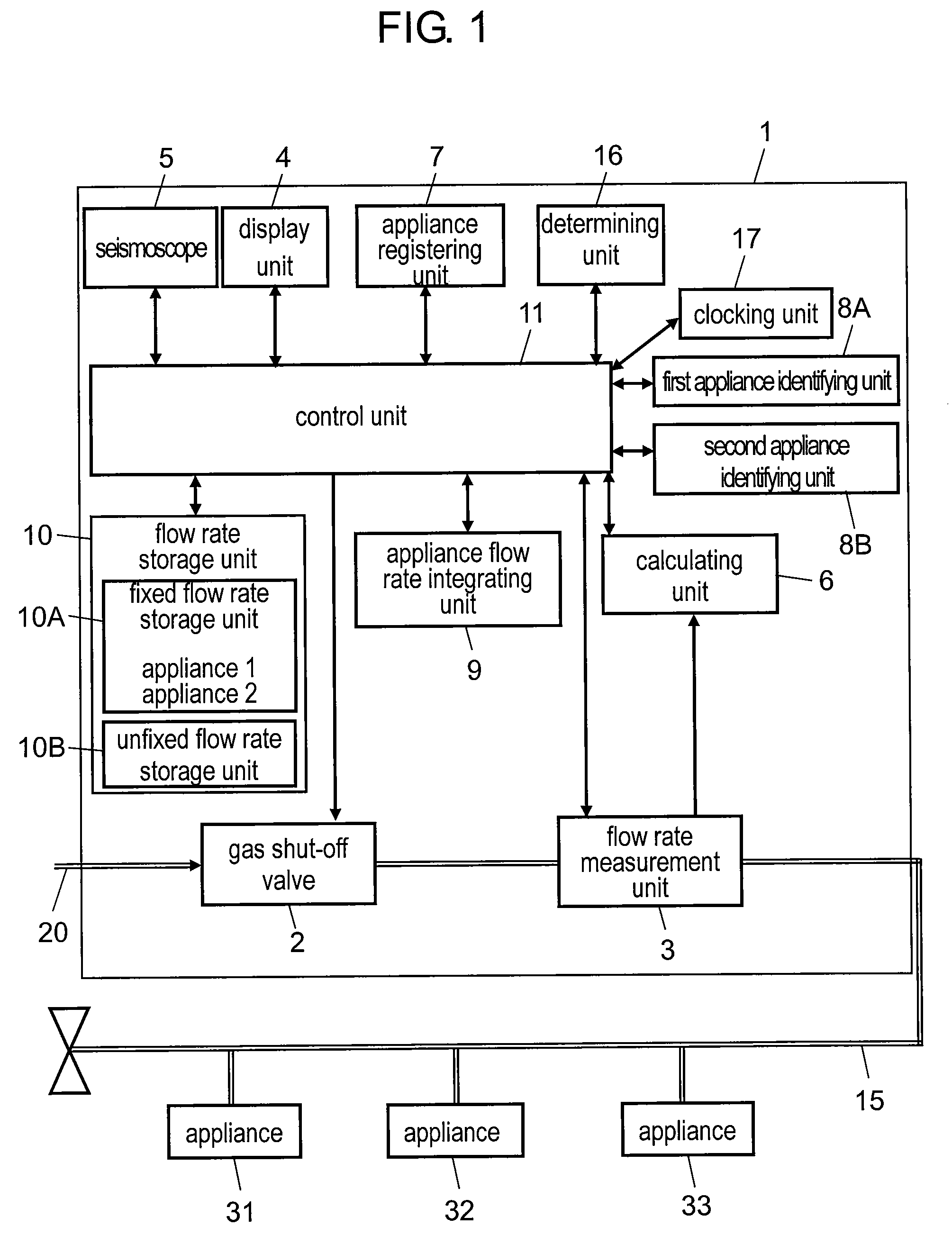
[0037]FIG. 1 is a function block diagram showing the configuration of a flow rate measuring device in accordance with an exemplary embodiment of the present invention. Flow rate measuring device 1 is disposed in a midway of gas supply pipe 20, and a pipe as flow channel 15 on the downstream side thereof is connected to appliances 31 to 33, namely two or more appliances installed in each customer house. Appliances 31 to 33 are a first gas appliance, a second gas appliance, and a third gas appliance that are connected to flow channel 15.

[0038]The inside of flow rate measuring device 1 is provided with gas shut-off valve 2 and flow rate measurement unit 3 disposed in flow channel 15, display unit 4, seismoscope 5, calculating unit 6, and control unit 11. Flow rate measurement unit...


PUM


Abstract

A flow rate measuring device has a flow rate measurement unit, an appliance registering unit, a calculating unit, a determining unit, a first appliance identifying unit, and a second appliance identifying unit. The appliance registering unit stores at least first gas flow rate variation profiles on activation of respective gas appliances coupled to a flow channel, and second gas flow rate variation profiles based on the control specific to the respective gas appliances. The first appliance identifying unit identifies which gas appliance is activated based on the first gas flow rate variation profiles on activation. When a determining unit detects a stop of any of gas appliances, the second appliance identifying unit identifies a gas appliance in continuous use by using the second gas flow rate variation profiles based on the control specific to the respective gas appliances.

Description

RELATED APPLICATIONS[0001]This application is a continuation of PCT / JP2007 / 073752, filed on Dec. 10, 2007, which claims priority to Japanese Application No. JP2006-332988, filed on Dec. 11, 2006. The entire contents of these applications are incorporated herein by reference.BACKGROUND OF THE INVENTION[0002]1. Field of the Invention[0003]The present invention relates to a flow rate measuring device that is installed at the inlet of a gas supply pipe in each household and is applied to a gas meter for measuring the gas flow rate. Specifically, the present invention relates to a technique for applying such a gas meter and identifying (specifying) a gas appliance in use in order to provide a new billing scheme and service, such as a fee by gas appliance, responsive to a used appliance type and its using method.[0004]2. Background Art[0005]A gas meter having a built-in gas flow rate measuring device is generally attached to the inlet of a gas supply line in each household. A billing sche...

Claims


Application Information

Patent Timeline
IPC IPC(8): G01F1/00G01F1/66G06F19/00G01F3/22
CPCG01F15/0755G01F1/66Y10T137/8593
Inventor UMEKAGE, YASUHIROMIYATA, HAJIMEKAMON, KENICHI
Owner PANASONIC CORP
Why Eureka
Try Eureka