Grease injection device

A grease injection device and grease bag technology, which is applied to engine components, engine lubrication, mechanical equipment, etc., can solve the problems of complicated process, high viscosity of lubricating grease, and difficult to control, so as to improve the utilization rate of grease and shorten the flow path of grease , The effect of small grease injection resistance

Inactive Publication Date: 2016-04-13
CHONGQING UNIVERSITY OF SCIENCE AND TECHNOLOGY
View PDF6 Cites 2 Cited by
  • Summary
  • Abstract
  • Description
  • Claims
  • Application Information

AI Technical Summary

Problems solved by technology

Due to the high viscosity and poor fluidity of the lubricating grease, the current grease injection equipment needs to take auxiliary measures to inject the grease in the grease bag, such as pressing the oil bag by hand, or using an auxiliary mechanical structure with a pressure plate and a spring, but the process is complicated , not easy to control, if the grease is used up, it is necessary to remove the oil bag repeatedly to replenish the grease, which is inconvenient to operate, and the repeated removal of the grease bag will easily cause the grease injection equipment to be polluted by dust, etc., resulting in a decline in the quality of the grease

Method used


Image

  • Grease injection device

Examples


Embodiment Construction

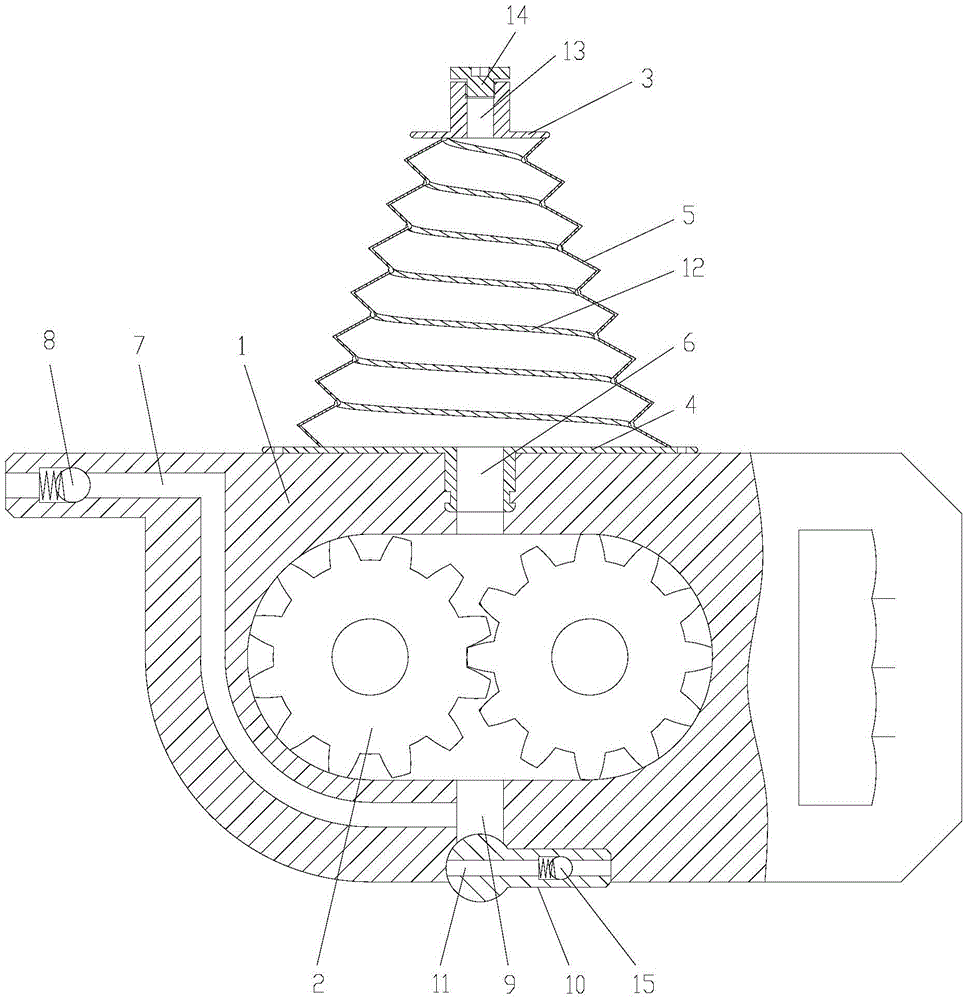
[0013] figure 1 It is a schematic diagram of the structure of the present invention, as shown in the figure: the grease injection device of this embodiment includes a device housing 1, two gears 2 installed in the inner cavity of the device housing 1 to form a gear pump structure, and fixed on the device housing 1 and connected with the device A grease bag connected to the oil suction cavity in the shell 1; the grease bag includes an upper connecting plate 3, a lower connecting plate 4 and a tapered bag body 5 fixed between the upper connecting plate 3 and the lower connecting plate 4; the lower connecting plate 4 There is an oil outlet 6 connecting the inner cavity of the conical bag body 5 and the oil suction cavity of the device shell 1, and the two gears 2 are installed in the inner cavity of the device shell 1 and meshed with each other, so that the two gears 2 and the device shell 1 The gear pump structure is formed between the two gears 2. The inner cavity of the device...


PUM


Abstract

The invention discloses a grease injection device which comprises a device shell, two gears arranged in an inner cavity of the shell to form a gear pump structure and a grease bag fixed to the device shell and communicated with an oil suction cavity in the device shell. The grease bag comprises an upper connecting plate, a lower connecting plate and a tapered bag body fixed between the upper connecting plate and the lower connecting plate. The lower connecting plate is provided with an oil outlet for making an inner cavity of the tapered bag body communicated with the oil suction cavity of the device shell. According to the grease injection device, the grease bag and a pump body are combined into a whole, the grease flow path is short, the grease injection resistance is small, use is convenient, labor is saved, the grease in the tapered grease bag of the structure is fully sucked out conveniently, and the grease utilization rate can be increased.

Description

technical field [0001] The invention relates to the technical field of grease lubrication, in particular to a grease injection device. Background technique [0002] Usually, mechanical parts need to be injected with a certain amount of grease during assembly and maintenance. For example, bearings are mostly lubricated by grease, which can ensure the lubrication of parts, reduce relative friction and improve the reliability of parts. Due to the high viscosity and poor fluidity of the lubricating grease, the current grease injection equipment needs to take auxiliary measures to inject the grease in the grease bag, such as pressing the oil bag by hand, or using an auxiliary mechanical structure with a pressure plate and a spring, but the process is complicated , not easy to control, if the grease is used up, it is necessary to remove the oil bag repeatedly to replenish the grease, which is inconvenient to operate, and the repeated removal of the grease bag will easily cause the...

Claims


Application Information

Patent Timeline
IPC IPC(8): F16N7/38
CPCF16N7/38
Inventor 孟杰李云松
Owner CHONGQING UNIVERSITY OF SCIENCE AND TECHNOLOGY
Why Eureka
Try Eureka