Workpiece mounting and positioning device convenient to dismount

A technology with convenient installation, positioning and disassembly. It is used in positioning devices, metal processing mechanical parts, machine tool parts, etc., and can solve problems such as prolonged processing time, troublesome disassembly, and difficult workpiece positioning.

Pending Publication Date: 2016-06-29
嵊州滨远工艺品有限公司
View PDF5 Cites 4 Cited by
  • Summary
  • Abstract
  • Description
  • Claims
  • Application Information

AI Technical Summary

Problems solved by technology

However, the clamping of these workpieces often requires pressing the surface of the workpiece, which easily causes damage to the surface quality of the workpiece
However, some supporting installation methods make it difficult to firmly position the workpiece.
Moreover, in some installation and positioning methods of f

Method used


Image

  • Workpiece mounting and positioning device convenient to dismount

Examples


Embodiment Construction

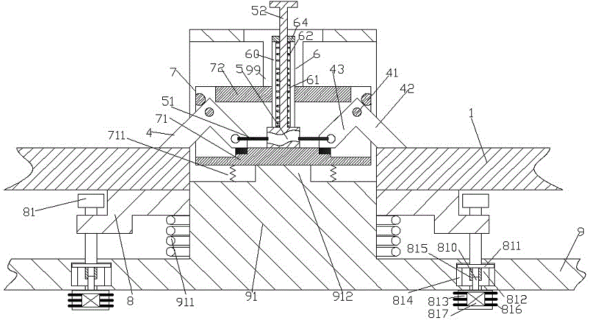
[0007] Combine below figure 1 The present invention will be described in detail.

[0008] According to an embodiment of the present invention, a device for installing and positioning a workpiece that is easy to assemble and disassemble is used for installing and positioning the workpiece 1, and includes a fixed frame 9, which is installed in the inner cavity of a fixed column 91 of the fixed frame 9 and The movable locking device 7 that can slide up and down along the guide rail 99 fixed in the inner cavity, and the telescopic reset between the fixed upright 91 and the bottom wall 71 of the movable locking device 7 Spring 711, wherein, the fixed column 91 is covered with a pressure plate 8 pressed by the pressure positioning spring 911 and guided and limited by the limit column 81, and the movable clamping device 7 includes symmetrically arranged Two pivoting arms 4, each pivoting arm 4 is pivotally connected to a respective pivot pin 41 fixed on the shell wall of the movable...


PUM


Abstract

The invention discloses a workpiece mounting and positioning device convenient to dismount, and the workpiece mounting and positioning device is used for mounting and positioning a workpiece (1). The workpiece mounting and positioning device comprises a fixed mount (9), a movable blocking device (7) which is mounted in an inner cavity of a fixedly arranged stand column (91) of the fixed mount (9) and is capable of sliding up and down along a guider rail (99) fixedly arranged in the inner cavity, and a telescopic return spring (711) which is arranged between the fixedly arranged stand column (91) and a bottom wall (71) of the movable blocking device (7), wherein top pressure plates (8) which are jacked by jacking and positioning springs (911) and are guided and limited by limiting posts (81) are arranged on the fixedly arranged stand column (91) in a sleeved manner.

Description

technical field [0001] The invention relates to the field of workpiece clamping, in particular to a workpiece installation and positioning device which is convenient for disassembly and assembly. Background technique [0002] In the industry, it is usually necessary to perform chucking and positioning for roughly sheet-like workpieces. However, the clamping of these workpieces often requires pressing the surface of the workpiece, which easily causes damage to the surface quality of the workpiece. However, it is difficult to firmly locate the workpiece in some supporting installation methods. Moreover, in some installation and positioning methods of fastening and clamping, its disassembly is relatively troublesome. This is likely to cause waste of work and operation time in the case of mass operations that require frequent clamping and dismounting of workpieces, thereby prolonging the processing time and possibly causing damage to the workpieces, and increasing the operatin...

Claims


Application Information

Patent Timeline
IPC IPC(8): B23Q3/06
CPCB23Q3/067B23Q2240/002
Inventor 朱淮智
Owner 嵊州滨远工艺品有限公司
Why Eureka
Try Eureka