Pneumatic lifting device

A kind of pneumatic lifting and gas technology, applied in the direction of lifting device, lifting frame, gas-liquid shock absorber, etc., can solve the problem that the gas spring cannot meet the needs of use, so as to enhance the new energy of the product, enhance the experience effect, and reduce the production and processing cost. Effect

Inactive Publication Date: 2016-07-27
CHANGZHOU LANT GAS SPRING CO LTD
View PDF7 Cites 0 Cited by
  • Summary
  • Abstract
  • Description
  • Claims
  • Application Information

AI Technical Summary

Problems solved by technology

[0003] In order to overcome the deficiency that the existing gas springs cannot meet the needs of use, the present invention provides a pneumatic lifting device

Method used


Image

  • Pneumatic lifting device
  • Pneumatic lifting device
  • Pneumatic lifting device

Examples


Embodiment Construction

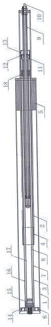
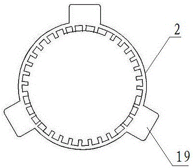
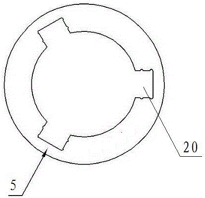
[0025] like Figure 1-6 It is a structural schematic diagram of the present invention, a pneumatic lifting device, including an outer tube 1, an outer tube 2 and an air spring 3, the outer tube 2 is placed in the outer tube 1, the gas spring 3 is placed in the outer tube 2, and the The junction of the outer tube 2 and the outer tube 1 is provided with a guide sleeve 2 5, one end of the outer tube 2 and the gas spring 3 is fixedly connected as one, and the other end is provided with a guide sleeve 4, the connection between the outer tube 1 and the gas spring 3 Spacers 6 are provided between them.

[0026] According to another embodiment of the present invention, it further includes that the gas spring 3 is composed of an inner tube 7, an oil tube 8, a piston rod body 9, a push rod 10, a ventilating support 11, an oil seal 12 and a rear top sleeve 13. The oil pipe 8 is placed in the inner pipe 7, the piston rod body 9 is placed in the oil pipe 8, the push rod 10 is placed in th...


PUM


Abstract

The invention relates to the technical field of lifting devices, in particular to a pneumatic lifting device. The pneumatic lifting device comprises an outer sleeve, an outer pipe and a gas spring. The outer pipe is arranged inside the outer sleeve. The gas spring is arranged inside the outer pipe. A second guide sleeve is arranged at the junction between the outer pipe and the outer sleeve. One end of the outer pipe and one end of the gas spring are fixedly connected to be a whole, and a first guide sleeve is arranged at the other end of the outer pipe and the other end of the gas spring. A gasket is arranged between the outer sleeve and the gas spring. According to the pneumatic lifting device, full rigid locking of a lifting mechanism can be achieved in any positions and directions, the descending force value and the ascending force value are uniform, downwards pressing is easily achieved, and the using limitation of a pneumatic lifting system is enlarged.

Description

technical field [0001] The invention relates to the technical field of lifting devices, in particular to a pneumatic lifting device. Background technique [0002] At present, the lockable gas spring is a lifting system that is widely used in daily life, especially in office furniture. It is the main component of the lifting table. The table used in the prior art cannot be rigidly locked. It is elastic, and the force value is too large when it is lowered to a low position, and the operation is very limited. And adjustment is loaded down with trivial details, lacks simplicity. The size tolerance of the outer casing steel pipe used in the pneumatic lifting system in the prior art is too large and uneven, which leads to increased friction and shaking when the pneumatic lifting system is raised and lowered, which directly leads to the performance of the pneumatic lifting system. Contents of the invention [0003] In order to overcome the deficiency that the existing gas sprin...

Claims


Application Information

Patent Timeline
Patent Type & Authority Applications(China)
IPC IPC(8): B66F7/28B66F7/00F16F9/06
CPCB66F7/28B66F7/00F16F9/06
Inventor 陶声华
Owner CHANGZHOU LANT GAS SPRING CO LTD
Why Eureka
Try Eureka