
Method and device for determining location information of sub-subsystem in distributed collaborative system

A technology of position information and cooperative system, applied in the field of electronics, can solve the problems of non-coincidence of position centers, large position information error of the main sub-system of the sub-sub-system and the main sub-system, etc.

Active Publication Date: 2018-09-07
BEIJING INST OF RADIO METROLOGY & MEASUREMENT
View PDF4 Cites 0 Cited by
  • Summary
  • Abstract
  • Description
  • Claims
  • Application Information

AI Technical Summary

Problems solved by technology

However, in actual situations, the position center of the main subsystem does not coincide with the position center of the main calibration system equipment, and the position center of the sub-subsystem does not coincide with the position center of the sub-calibration system equipment, such as figure 1 As shown, the coordinate system is established with the position center O of the main calibration system equipment as the coordinate origin, but the position center C of the main subsystem does not coincide with the position center O of the main calibration system equipment. Therefore, the prior art uses the calibration equipment to obtain The error of the position information of the auxiliary subsystem relative to the main subsystem is relatively large

Method used


Image

  • Method and device for determining location information of sub-subsystem in distributed collaborative system
  • Method and device for determining location information of sub-subsystem in distributed collaborative system
  • Method and device for determining location information of sub-subsystem in distributed collaborative system

Examples


Embodiment 1

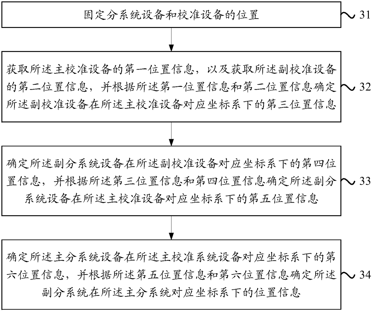
[0048] Embodiment 1 provides a method for determining the location information of the sub-system in a distributed collaborative system, which is used to solve the problem that the position center of the sub-system and the calibration equipment do not coincide in the prior art. The location information error of the subsystem is relatively large. The specific flow chart of the method is shown in image 3 shown, including the following steps:

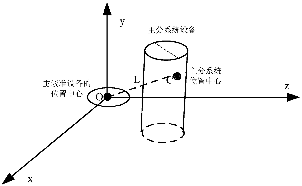
[0049] Step 31: Fix the positions of subsystem equipment and calibration equipment, wherein the subsystem equipment includes main subsystem equipment and auxiliary subsystem equipment, and the calibration equipment includes main calibration system equipment and auxiliary calibration system equipment.

[0050] As mentioned above, when determining the location information of the sub-system relative to the main sub-system according to the location information of the main sub-system, install the main sub-system equipment and sub-subsystem equ...

Embodiment 2

[0100] Embodiment 1 provides a method for determining the location information of the sub-subsystem in the distributed collaborative system. Correspondingly, the embodiment of the present invention provides a device for determining the location information of the sub-subsystem in the distributed collaborative system, for It solves the problem in the prior art that the obtained position information of the sub-system relative to the main sub-system has a large error due to the misalignment of the position centers of the sub-system equipment and the calibration equipment. The specific structure of the device is as Figure 5 As shown, the device includes:

[0101] The fixing unit 51, the acquiring unit 52, the first determining unit 53 and the second determining unit 54, wherein:

[0102] The fixing unit 51 can be used to fix the positions of the subsystem equipment and the calibration equipment, wherein the subsystem equipment includes the main subsystem equipment and the auxili...


PUM


Abstract

The invention discloses a method and device for determining position information of an auxiliary subsystem in a distributed cooperative system. The method comprises the following steps: positions of subsystems and calibration devices are fixed; first position information and second position information of a main calibration system device and an auxiliary calibration system device are obtained, and third position information of the auxiliary calibration system device in a coordinate system corresponding to the main calibration system device is determined; fourth position information of an auxiliary subsystem device in a coordinate system corresponding to the auxiliary calibration system device is determined; fifth position information of the auxiliary subsystem device in the coordinate system corresponding to the main calibration system device is determined; sixth position information of a main subsystem device in the coordinate system corresponding to the main calibration system device is determined; position information of an auxiliary subsystem in a coordinate system corresponding to a main subsystem is determined. The method and device for determining position information of the auxiliary subsystem in the distributed cooperative system can help solve a problem that error of obtained position information of the auxiliary subsystem relevant to the main subsystem is large because subsystem position centers and corresponding position centers of the calibration devices are superposed by default in technologies of the prior art.

Description

technical field [0001] The invention relates to the field of electronic technology, in particular to a method and a device for determining the location information of a sub-subsystem in a distributed collaborative system. Background technique [0002] At present, in many application scenarios, such as distributed collaborative systems such as navigation of vehicles, observation of atmospheric physics, and movement of celestial bodies, it is necessary to perform positioning processing on each subsystem in the system. The location information of a system (main subsystem) determines the location information of another subsystem (secondary subsystem) relative to the main subsystem. [0003] In the prior art, when obtaining the location information of the sub-system relative to the main sub-system, the main sub-system and the sub-system are respectively provided with main sub-system equipment and sub-subsystem equipment, and the main sub-system equipment and sub-subsystem The eq...

Claims


Application Information

Patent Timeline
Patent Type & Authority Patents(China)
IPC IPC(8): G01S19/47G01S19/40G01C21/16
CPCG01C21/165G01S19/40G01S19/47
Inventor 刘博宇李宏宇谢淑香关宏凯曹宇周应强李闯
Owner BEIJING INST OF RADIO METROLOGY & MEASUREMENT
Learn More