Boost converter and control method therefor

A technology of step-up converter and conversion circuit, which is applied in the direction of control/regulation system, DC power input conversion to DC power output, instruments, etc. It can solve the problem of reducing the total harmonic distortion rate of input current and increasing input current. Ripple, current discontinuity and other problems, to achieve the effect of reducing harmonic content, continuous input current, and improving efficiency

Active Publication Date: 2016-09-28
江苏汉尔源智能科技有限公司
View PDF6 Cites 6 Cited by
  • Summary
  • Abstract
  • Description
  • Claims
  • Application Information

AI Technical Summary

Problems solved by technology

But in the light load state, even if the continuous current control mode is used, there will still be an intermittent current area
Especially when the output voltage increases, the input current will appear discontinuous at the zero-crossing point of the voltage, which will increase the ripple of the input current and cannot reduce the total harmonic distortion (THD) of the input current well.

Method used


Image

  • Boost converter and control method therefor
  • Boost converter and control method therefor
  • Boost converter and control method therefor

Examples


Embodiment 1

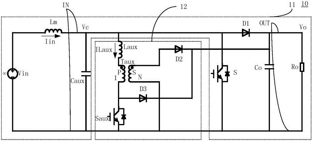
[0028] Such as figure 1 Shown is a specific embodiment of the present invention. The boost converter in this embodiment includes a boost conversion circuit 11 and a resonant circuit 12 . The boost conversion circuit 11 is a boost converter, including an input terminal IN, an output terminal OUT, a main power inductor Lm, a main power switch tube S, a main power diode D1, and an output capacitor Co. The main power inductor Lm is connected in series In the input terminal IN of the boost conversion circuit 11, the main power switch tube S is connected in parallel with the input terminal IN of the boost conversion circuit 11, and when it is closed, the input voltage of the input terminal IN is the main power switch S. The power inductor Lm is charged, and when it is disconnected, the input terminal IN of the boost conversion circuit 11 supplies power to the load of the output terminal OUT. The resonant circuit 12 includes a resonant capacitor Caux, an auxiliary switch Saux, an a...

Embodiment 2

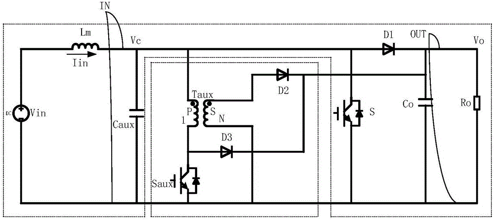
[0043] Such as figure 2 Shown is another specific embodiment of the present invention, and figure 1 The specific embodiment shown differs in that in this embodiment the resonant inductance Laux is integrated in the auxiliary transformer Taux.

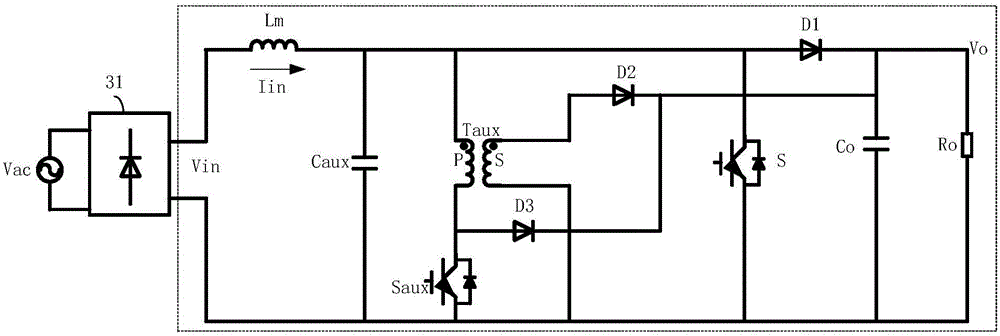
[0044] Such as image 3 As shown, the boost conversion device of the present invention is applied to an AC / DC conversion device to perform power factor correction. The input end of the boost conversion device is connected to a rectifier bridge 31, and the rectifier bridge 31 rectifies the AC input Vac It is a direct current Vdc output, and is output to a step-up conversion device. The current harmonics of the AC / DC conversion device can be better reduced by the boost conversion device of the present invention. At the same time, since the circuit of the present invention realizes the soft switching technology, a higher frequency drive signal can be used to control the switching of the switch in the circuit. Turn on or turn off, so th...

Embodiment 3

[0047] Such as Figure 6 As shown, the present invention also provides another preferred control method. The current sampling device is used to sample the input current Iin of the boost converter 61 to obtain the sampling current Ic. The current sampling device includes a current transformer CT, a resistor R1, A capacitor C1, the input end of the current transformer CT is connected to the input end of the boost converter 61, the output end of the current transformer CT is connected in series with the resistor R1 and the capacitor C1, the first capacitor of the capacitor C1 The terminal serves as the output end of the sampling current and is connected to a drive control circuit, which controls the switch S and Saux according to the magnitude relationship between the sampling current Ic and the first set value I1 and the second set value I2:

[0048] When Ic

[0049...


PUM


Abstract

The invention relates to a boost converter and a control method therefor. The boost converter comprises a boot conversion circuit and a resonance circuit. The resonance circuit comprises a resonance capacitor, an auxiliary transformer, a resonance inductor, and an auxiliary switch. The resonance capacitor is in parallel connection with the input end of the boost conversion circuit, so as to receive an input voltage of the resonance circuit, and to supply an auxiliary current for the input end of the boost conversion circuit. The primary side of the auxiliary transformer is in series connection with the resonance inductor and the auxiliary switch, and then is in parallel connection with the resonance capacitor, and receives the input voltage of the resonance circuit. The secondary side of the auxiliary transformer is in parallel connection with the output end of the boost conversion circuit. Compared with the prior art, the boost converter can maintain the continuity of the input current, reduces the harmonic component of the current, can achieve the soft switching of a switching device in the circuit, and improves the efficiency of the circuit.

Description

technical field [0001] The invention relates to a boost converter, in particular to a boost converter with a resonant circuit and a control method thereof. Background technique [0002] When traditional boost converters are used in high-power applications, in order to solve the shortcomings of electromagnetic interference and large switching losses in the current discontinuous mode, the continuous current control mode is usually used. But in the light load state, even if the continuous current control mode is used, there will still be an area of ​​current discontinuity. Especially when the output voltage increases, the input current will be discontinuous at the zero-crossing point of the voltage, which will increase the ripple of the input current and fail to reduce the total harmonic distortion (THD) of the input current well. Contents of the invention [0003] The purpose of the present invention is to provide a boost converter and its control method in order to overcom...

Claims


Application Information

Patent Timeline
Patent Type & Authority Applications(China)
IPC IPC(8): H02M3/155H02M3/335H02M1/14H02M1/32H02M1/42
CPCH02M1/14H02M1/32H02M1/4225H02M1/4241H02M3/155H02M3/335H02M1/0058Y02B70/10
Inventor 曼苏乐
Owner 江苏汉尔源智能科技有限公司
Why Eureka
Try Eureka