
Novel pan-shot unmanned aerial vehicle

A technology for panoramic shooting and drones, applied in the field of unmanned aerial vehicles, can solve the problems of drones appearing, wasting manpower and time, and achieve the effects of reducing labor, improving quality, and stable and reliable pictures and videos.

Inactive Publication Date: 2016-10-26
HUIXINGHAI SCI & TECH TIANJIN CO LTD
View PDF3 Cites 14 Cited by
  • Summary
  • Abstract
  • Description
  • Claims
  • Application Information

AI Technical Summary

Problems solved by technology

[0003] In the existing structure, whether it is a multi-axis or a single-blade UAV, most of its video recording devices are installed in the gimbal, but its disadvantage is that when the UAV changes from a hovering state to a moving state, no one The camera will appear in the recorded photos or videos due to the change of the tilt angle.
For the above-mentioned photos and videos, it will inevitably cause great inconvenience and waste a lot of manpower and time in the post-editing.

Method used


Image

  • Novel pan-shot unmanned aerial vehicle
  • Novel pan-shot unmanned aerial vehicle
  • Novel pan-shot unmanned aerial vehicle

Examples


Embodiment 1

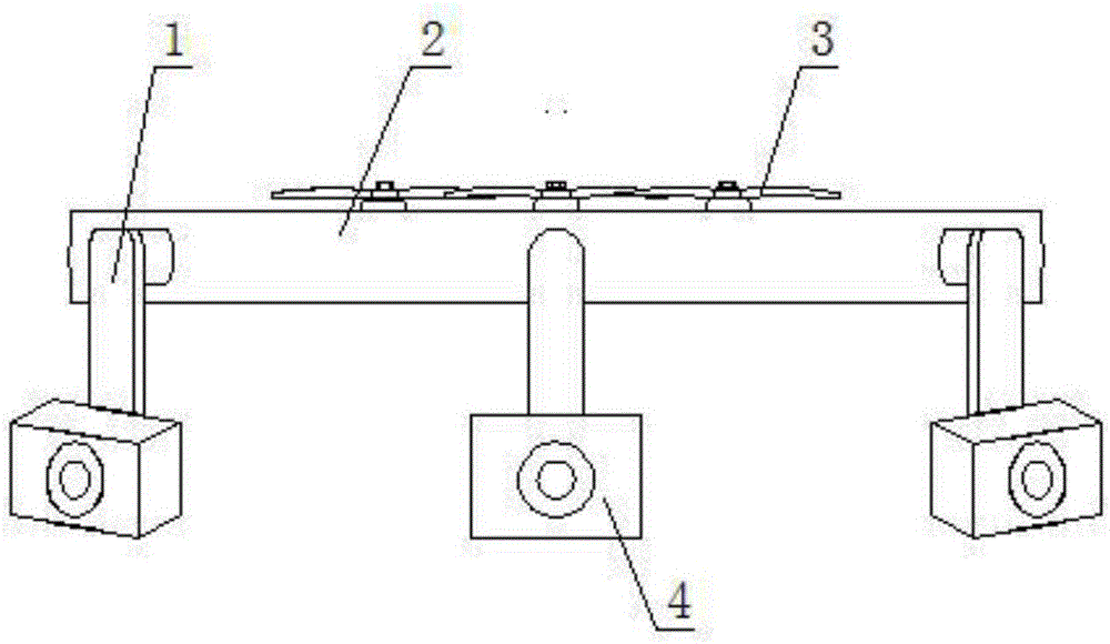
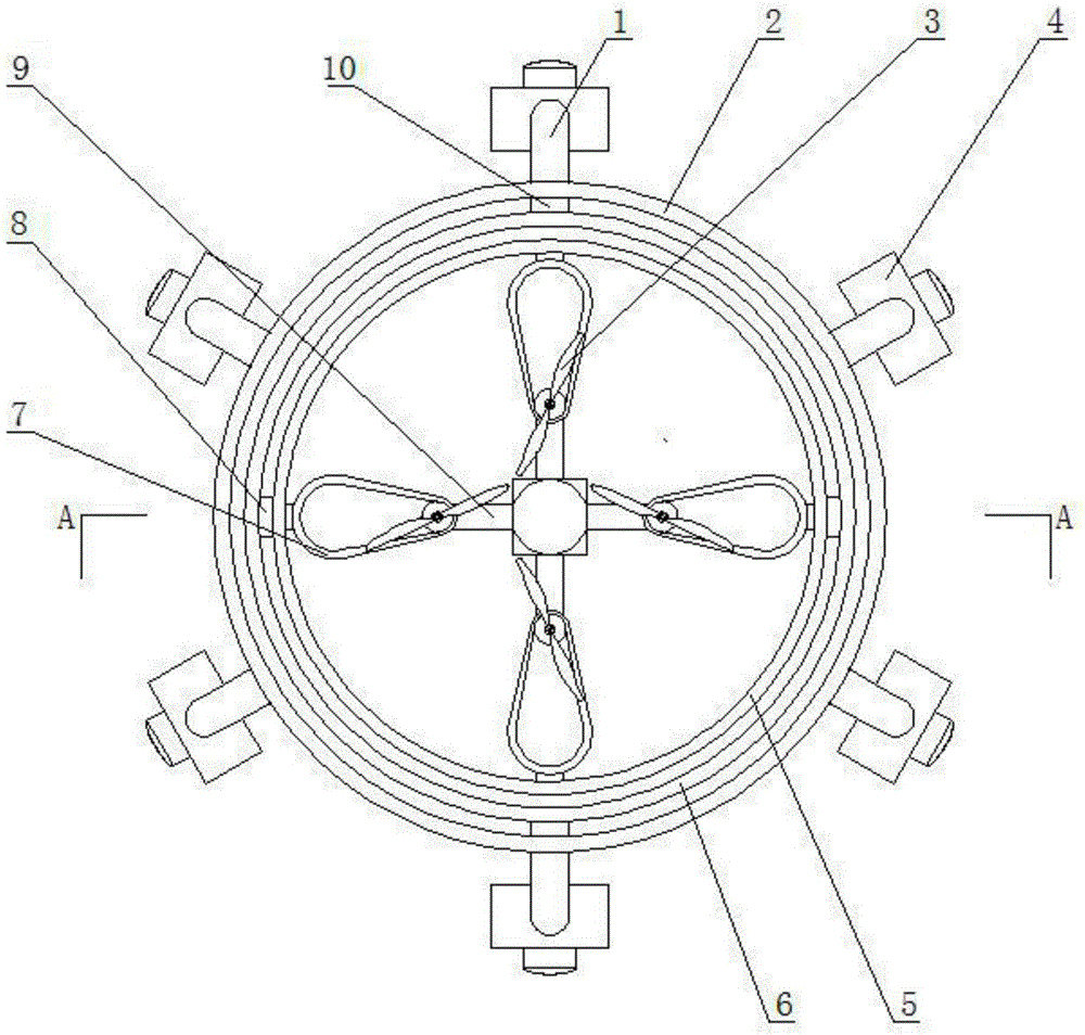
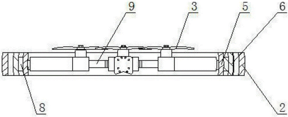
[0028] Example 1 as Figure 1 to Figure 4 As shown, in this embodiment, the mounting frame includes an inner ring frame 5, a middle ring frame 6 and an outer ring frame 2, and the inner ring frame, the middle ring frame and the outer ring frame are closed rings made of hard materials , the inner ring frame, the middle ring frame and the outer ring frame are concentrically spaced, and the inner edge of the inner ring frame is evenly spaced with a plurality of connecting clips 7, and the inner ends of the connecting clips are jointly fixed with the UAV. The body, the drone and the inner ring frame are located in the same horizontal plane, and the outer edge of the inner ring frame is installed on both sides along the diameter direction through an inner pan platform shaft 8 and the inner edge of the middle ring frame. The diameter position of the outer edge of the frame perpendicular to the extension direction of the inner pan-tilt shaft is respectively installed by rotation of a...

Embodiment 2

[0030] Example 2 as Figure 5 and Figure 6 As shown, in this embodiment, the mounting frame includes an inner ring frame, a middle ring frame and an outer ring frame, and the inner ring frame, the middle ring frame and the outer ring frame are closed rings made of hard materials. The ring frame, the middle ring frame and the outer ring frame are concentrically spaced, and a plurality of connecting clips are evenly spaced on the inner edge of the inner ring frame, and the inner ends of the connecting clips are jointly fixed with the body of the drone. The unmanned aerial vehicle and the inner ring frame are located in the same horizontal plane, and the outer edge of the inner ring frame along the two sides of the diameter direction is respectively installed by rotating the inner edge of an inner pan-tilt shaft and the middle ring frame, and the outer edge of the middle ring frame and the The diameter positions perpendicular to the extension direction of the inner pan-tilt sha...


PUM


Abstract

The invention relates to the field of unmanned aerial vehicles, in particular to a novel pan-shot unmanned aerial vehicle, comprising a body of the unmanned aerial vehicle. An installation frame is installed in the body of the unmanned aerial vehicle, the outside end of the installation frame extends out of the body of the unmanned aerial vehicle, multiple pieces of videography equipment are uniformly installed at the ends, positioned at the outer sides of paddles installed on the body, of the installation frame at intervals, the installation frame comprises an inner-ring frame, a middle-ring frame and an outer-ring frame which are closed circular rings made of rigid materials, the inner-ring frame, the middle-ring frame and the outer-ring frame are concentrically arranged in a sleeving way at intervals, the body of the unmanned aerial vehicle is fixedly installed at the inner edge, along the end face level to the inner-ring frame, of the inner-ring frame, the ends of the two sides of the outer edge of the inner-ring frame along the diameter direction are rotationally installed on the inner edge of the middle-ring frame through inner cloud deck shafts, and the diameter positions, perpendicular to the extension directions of the inner cloud deck shafts, at the outer edge of the middle-ring frame are rotationally installed on the inner edge of the outer-ring frame through outer cloud deck shafts.

Description

technical field [0001] The invention relates to the field of unmanned aerial vehicles, in particular to a novel unmanned aerial vehicle capable of panoramic shooting. Background technique [0002] With the development and innovation of technology, civilian drones are widely used in aerial photography, survey and other image acquisition tasks due to their small structure and easy manipulation. [0003] In the existing structure, whether it is a multi-axis or a single-blade UAV, most of its video recording devices are installed in the gimbal, but its disadvantage is that when the UAV changes from a hovering state to a moving state, no one The camera will appear in the recorded photos or videos due to the change of the tilt angle. For the above-mentioned photos and videos, it will inevitably cause great inconvenience and waste a lot of manpower and time in the post-editing. Contents of the invention [0004] The purpose of the present invention is to overcome the deficienci...

Claims


Application Information

Patent Timeline
IPC IPC(8): B64D47/08
CPCB64D47/08
Inventor 符星
Owner HUIXINGHAI SCI & TECH TIANJIN CO LTD
Learn More