A device and method for real-time measurement of flow field distribution at the tip of a compressor

A technology of flow field distribution and real-time measurement, applied in the field of compressors, can solve the problems of inability to obtain accurate value of airflow pressure in real time, limitations of accuracy and real-time performance, and dependence on theoretical calculation, etc., to achieve lightweight and soft cutting, high sensitivity, thickness thin effect

Active Publication Date: 2018-11-16
SHANGHAI JIAOTONG UNIV
View PDF8 Cites 0 Cited by
  • Summary
  • Abstract
  • Description
  • Claims
  • Application Information

AI Technical Summary

Problems solved by technology

There are three main research methods at present: theoretical model, numerical simulation, and experimental measurement (such as the measurement method of miniature five-hole pressure probe), etc. However, the distribution of the air flow field of the compressor in actual work will be different, so it cannot be real-time Get the exact value of the airflow pressure
At present, the acquisition of compressor blade tip pressure mostly relies on theoretical calculation and indirect measurement, which has great limitations in terms of accuracy and real-time performance.

Method used


Image

  • A device and method for real-time measurement of flow field distribution at the tip of a compressor
  • A device and method for real-time measurement of flow field distribution at the tip of a compressor
  • A device and method for real-time measurement of flow field distribution at the tip of a compressor

Examples


Embodiment Construction

[0036] Referring to the accompanying drawings of embodiments of the invention, the invention will be described in more detail below. However, this invention may be embodied in many different forms and should not be construed as limited to the embodiments set forth herein. Rather, these embodiments are provided so that this disclosure will be thorough and complete, and will fully convey the scope of the invention to those skilled in the art. In these drawings, the size and relative sizes of layers and regions may be exaggerated for clarity.

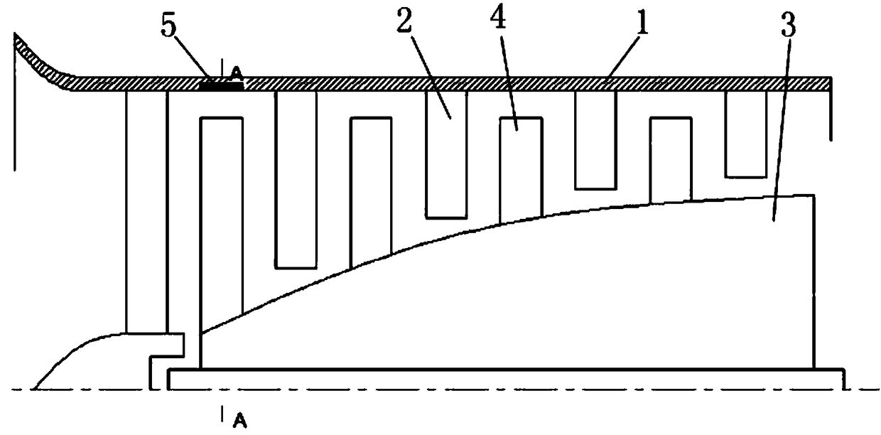
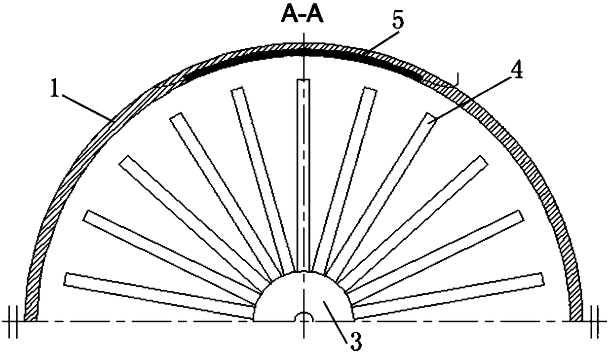
[0037] refer to figure 1 Generally, the compressor includes a coaxial stator and rotor, and the rotor is located inside the stator; wherein, the stator includes a casing 1 and several vanes 2 arranged on the inner wall of the casing 1, and the rotor includes a rotating shaft 3 and is arranged outside the rotating shaft 3 A number of moving blades 4 on the wall, the stator blades 2 and the moving blades 4 are set apart from each other in ...


PUM


Abstract

The invention provides a compressor blade tip flow field distribution real-time measurement device and method. A groove is arranged in an inner side wall of a casing corresponding to the blade tip of a movable blade of a compressor, and the groove is internally provided with a film sensor. The film sensor is provided with at least one piezoelectric transducer unit and at least one temperature sensor unit. The piezoelectric transducer unit is used for converting blade tip flow field pressure into a pressure electric signal as output, and the temperature sensor unit is used for converting blade tip environmental temperature into a temperature electric signal as output. A signal collection system is used to receive the pressure electric signal and the temperature electric signal on the film sensor, and to convert the pressure electric signal and the temperature electric signal into digital signals, thereby achieving display on a computer. The invention can accurately measure the pressure distribution condition of a compressor dynamic air flow filed without destroying feature conditions such as the flow of the air flow field, the boundary condition and the pressure distribution, and has important theoretical significance and practical values for improving the compressor dynamic feature prediction precision and the compressor design level.

Description

technical field [0001] The invention relates to the technical field of compressors, in particular to a real-time measuring device and method for the flow field distribution of a compressor blade tip. Background technique [0002] The compressor is an important part of the aero-engine, and it is of great significance to improve the aerodynamic performance of the engine by using the high-speed rotating blades to do work on the air to achieve the function of increasing the air pressure. Its dynamic characteristics have a very significant impact on the overall dynamic characteristics of the engine. It generally consists of two parts, the rotor and the stator. The rotor includes the rotor shaft and moving blades, and the stator includes the casing and stator blades. In order to prevent the rotor blade from colliding with the casing, the rotor in the compressor needs to leave a certain gap when it rotates at high speed. The pressure distribution of the blade tip has always been a...

Claims


Application Information

Patent Timeline
Patent Type & Authority Patents(China)
IPC IPC(8): G01M9/06
Inventor 荆建平季超王志强
Owner SHANGHAI JIAOTONG UNIV
Why Eureka
Try Eureka