Driving mechanism driving moving pieces to move back and forth on installation base in radial direction and chuck

A technology of reciprocating movement and driving mechanism, which is applied in the field of workpiece clamping devices, can solve problems affecting the normal use of the chuck, and achieve the effects of simple and reliable mechanical transmission process, accurate and stable position, and stable and reliable mechanical transmission mode

Active Publication Date: 2016-11-16
BEIJING XUANYU INTELLIGENT TECH CO LTD
View PDF9 Cites 15 Cited by
  • Summary
  • Abstract
  • Description
  • Claims
  • Application Information

AI Technical Summary

Problems solved by technology

[0004] Therefore, the technical problem to be solved by the present invention is to overcome the defect that the jaw drive mechanism of the chuck in the prior art interferes with the rotation of the chuck, which affects the normal use of the chuck, thereby providing a stable, non-wearing, non-contact chuck. The disc rotation forms an interference, safer and more reliable driving mechanism that drives the moving part to move back and forth radially on the mounting seat

Method used


Image

  • Driving mechanism driving moving pieces to move back and forth on installation base in radial direction and chuck
  • Driving mechanism driving moving pieces to move back and forth on installation base in radial direction and chuck
  • Driving mechanism driving moving pieces to move back and forth on installation base in radial direction and chuck

Examples


Embodiment 1

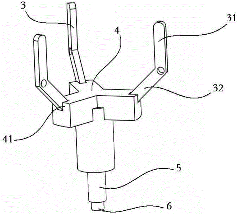
[0041] figure 1 It is a three-dimensional view of the driving mechanism that drives the moving part to move radially back and forth on the mounting seat provided in Embodiment 1 of the present invention, as shown in figure 1 As mentioned above, the driving mechanism for driving the moving part to move back and forth radially on the mounting base provided by this embodiment includes: a dial, which is rotatably arranged relative to the mounting base, and is positioned between the moving parts corresponding to the dialing part. Rotate in the plane determined by the radial direction and the axial direction of the mounting seat, and connect with the corresponding moving piece; the drive assembly has a toggle connecting part 41 that is distributed in the same way as the toggle. The toggle is hinged to the corresponding toggle connecting portion 41, and when the drive assembly moves back and forth along the axial direction of the mounting seat, it drives the toggle to rotate and driv...

Embodiment 2

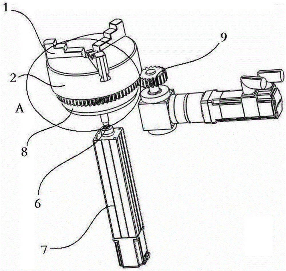
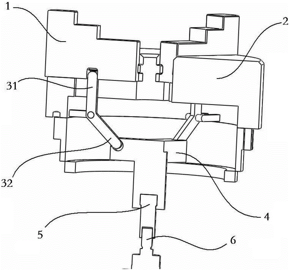
[0048] figure 2 It is a perspective view of the chuck provided in Embodiment 2 of the present invention; image 3 for figure 2 The cross-sectional view at A, such as figure 2 and 3 As shown, the chuck provided in this embodiment includes at least two jaws 1; the chuck body 2 is formed with radial grooves uniformly distributed on the disk surface, and each radial groove is provided with one jaw 1. At least two claws 1 near the center of the chuck body 2 form a clamping mouth, and the claws 1 can reciprocate along the radial groove to adjust the diameter of the clamping mouth size; and the driving mechanism for driving the moving part to move back and forth radially on the mounting seat described in the first embodiment, wherein the displacement part is the jaw 1 and the mounting seat is the chuck body 2 .

[0049] Driven by the telescopic power, the driving mechanism drives the claw 1 to move radially along the disk surface, and the clamping opening formed by the claw 1 ...


PUM


Abstract

The invention discloses a driving mechanism driving moving pieces to move back and forth on an installation base in the radial direction and a chuck. The driving mechanism comprises stirring pieces and a driving assembly. The stirring piece can rotate relative to the installation base and rotate in the plane determined by the radial direction of the moving pieces corresponding to the stirring pieces and the axial direction of the installation base, and the stirring pieces are connected with the corresponding moving pieces. The driving assembly is provided with stirring piece connecting parts, wherein distribution of the stirring piece connecting parts is consistent with that of the stirring pieces. The stirring pieces are hinged to the corresponding stirring piece connecting parts. When the driving assembly moves back and forth in the axial direction of the installation base, the stirring pieces are driven to rotate to drive the moving pieces to move back and forth in the radial direction of the installation base. According to the driving mechanism driving the moving pieces to move back and forth on the installation base in the radial direction and the chuck, a mechanical transmission assembly is simple in structure, stable and reliable, and non-interference rotation of the chuck can be achieved.

Description

technical field [0001] The invention relates to the technical field of workpiece clamping devices, in particular to a drive mechanism and chuck for driving a moving part to move back and forth radially on a mounting seat. Background technique [0002] The chuck utilizes the radial movement of the movable jaws evenly distributed on the chuck body to realize the clamping and positioning of the workpiece. The chuck is usually installed on a lathe, an external grinder or an internal grinder. The common electric chuck, chuck There is a helical wire on the disk body, and a threaded groove that matches the helical wire is provided at the bottom of the claw. The motor drives the transmission shaft to rotate, and the transmission shaft drives the helical wire to rotate, driving the claw to move radially, but this electric claw The drive mechanism is not suitable for rotatable chucks, because the radial movement of the jaws is driven by the rotation of the spiral coil wire, and the ro...

Claims


Application Information

Patent Timeline
Patent Type & Authority Applications(China)
IPC IPC(8): B23B31/16B23B31/02
CPCB23B31/02B23B31/16
Inventor 尹文彬张韬懿范立明王全武吴昊
Owner BEIJING XUANYU INTELLIGENT TECH CO LTD
Why Eureka
Try Eureka