Parking brake control unit with remote relieving function

A technology of parking brake and control unit, applied in the direction of brake, brake transmission, transportation and packaging, etc., can solve problems such as inability to guarantee mitigation, operator inability to use electrical signals, and control the state of electromagnetic pulse valves.

Active Publication Date: 2016-11-30
KNORR BREMSE BRAKE EQUIP SUZHOU CO LTD
View PDF6 Cites 4 Cited by
  • Summary
  • Abstract
  • Description
  • Claims
  • Application Information

AI Technical Summary

Problems solved by technology

[0002] When the locomotive is in the no-fire loopback mode, it usually needs other vehicles to drag it. At this time, the operator needs to trigger the parking release button on the console to control the pulse solenoid valve to be in the parking release state. If the operator misoperates, the pulse is not ensured. If the electromagnetic valve is in the state, there is no pressure input in the parking brake pipe, and i

Method used


Image

  • Parking brake control unit with remote relieving function

Examples


Embodiment Construction

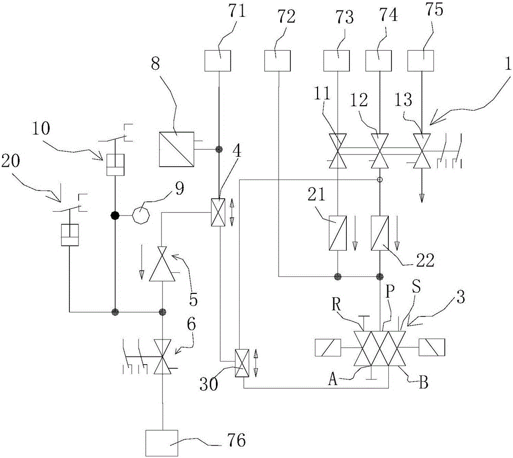
[0023] Such as figure 1 The shown parking brake control unit with remote release function includes a first stopcock 11 arranged on the pipeline for communicating with the main air pipe 73, a second stopcock 12 for communicating with the brake pipe 74, The third cock 13 for communicating with the average pipe, the parking brake unit also includes a pulse solenoid valve 3 for communicating with the parking brake cylinder 76, the first cock 11, the second The plug gates 12 communicate with the pulse solenoid valves 3 respectively, and the parking brake unit also includes a first two-way check valve 30, and the first two-way check valve 30 has a first end, a second end , the third end, the first end of the first two-way check valve 30 communicates with the pulse solenoid valve 3, and the second end of the first two-way check valve 30 communicates with the second plug 12 and the pulse solenoid valve 3, there is no conduction between the first end and the second end of the first tw...


PUM


Abstract

The invention discloses a parking brake control unit with a remote relieving function. The parking brake control unit comprises a first cock which is arranged on a pipeline and used for being communicated with a main air pipe, a second cock used for being communicated with a brake pipe and a third cock used for being communicated with an average pipe, and the parking brake unit further comprises a pulse solenoid valve used for being communicated with a parking brake cylinder; the first cock and the second cock are communicated with the pulse solenoid valve separately; the parking brake unit further comprises a first double check valve which has a first end, a second end and a third end, the first end of the first double check valve is communicated with the pulse solenoid valve, the second end of the first double check valve is communicated with the portion, between the second cock and the pulse solenoid valve, of the pipeline, the first end of the first double check valve and the second end of the first double check valve are not conductive, the first end of the first double check valve and the third end of the first double check valve are conductive, and the second end of the first double check valve and the third end of the first double check valve are conductive.

Description

technical field [0001] The present application relates to a parking brake control unit with remote release function. Background technique [0002] When the locomotive is in the no-fire loopback mode, it usually needs other vehicles to drag it. At this time, the operator needs to trigger the parking relief application button on the console to control the pulse solenoid valve to be in the parking relief state. If the operator misoperates, the pulse is not ensured. If the electromagnetic valve is in the state, there is no pressure input in the parking brake pipe, and its relief cannot be guaranteed, so that the locomotive cannot be returned safely without fire. In the prior art, another situation that usually occurs is that the electromagnetic pulse valve fails or the electromagnetic pulse valve is in a state of no power supply, and the operator cannot use electrical signals to control the state of the electromagnetic pulse valve, so that the locomotive cannot perform fire-free...

Claims


Application Information

Patent Timeline
IPC IPC(8): B60T13/26B60T13/68
CPCB60T13/26B60T13/683
Inventor 曼弗雷德·弗拉黄自立陆凤祥
Owner KNORR BREMSE BRAKE EQUIP SUZHOU CO LTD
Why Eureka
Try Eureka