Check patentability & draft patents in minutes with Patsnap Eureka AI!

a v-iron

A technology of V-groove and slider, which is used in the testing of machine/structural components, transmission devices, instruments, etc., can solve problems such as difficulty in operation, and achieve the effect of easy rotation

Active Publication Date: 2019-06-11
WUHAN MARINE MACHINERY PLANT
View PDF9 Cites 1 Cited by
  • Summary
  • Abstract
  • Description
  • Claims
  • Application Information

AI Technical Summary

Problems solved by technology

[0006] In order to solve the problem of difficult operation when rotating parts on the V-shaped iron, the embodiment of the present invention provides a V-shaped iron

Method used


Image

  • a v-iron
  • a v-iron

Examples


Embodiment Construction

[0021] In order to make the object, technical solution and advantages of the present invention clearer, the implementation manner of the present invention will be further described in detail below in conjunction with the accompanying drawings.

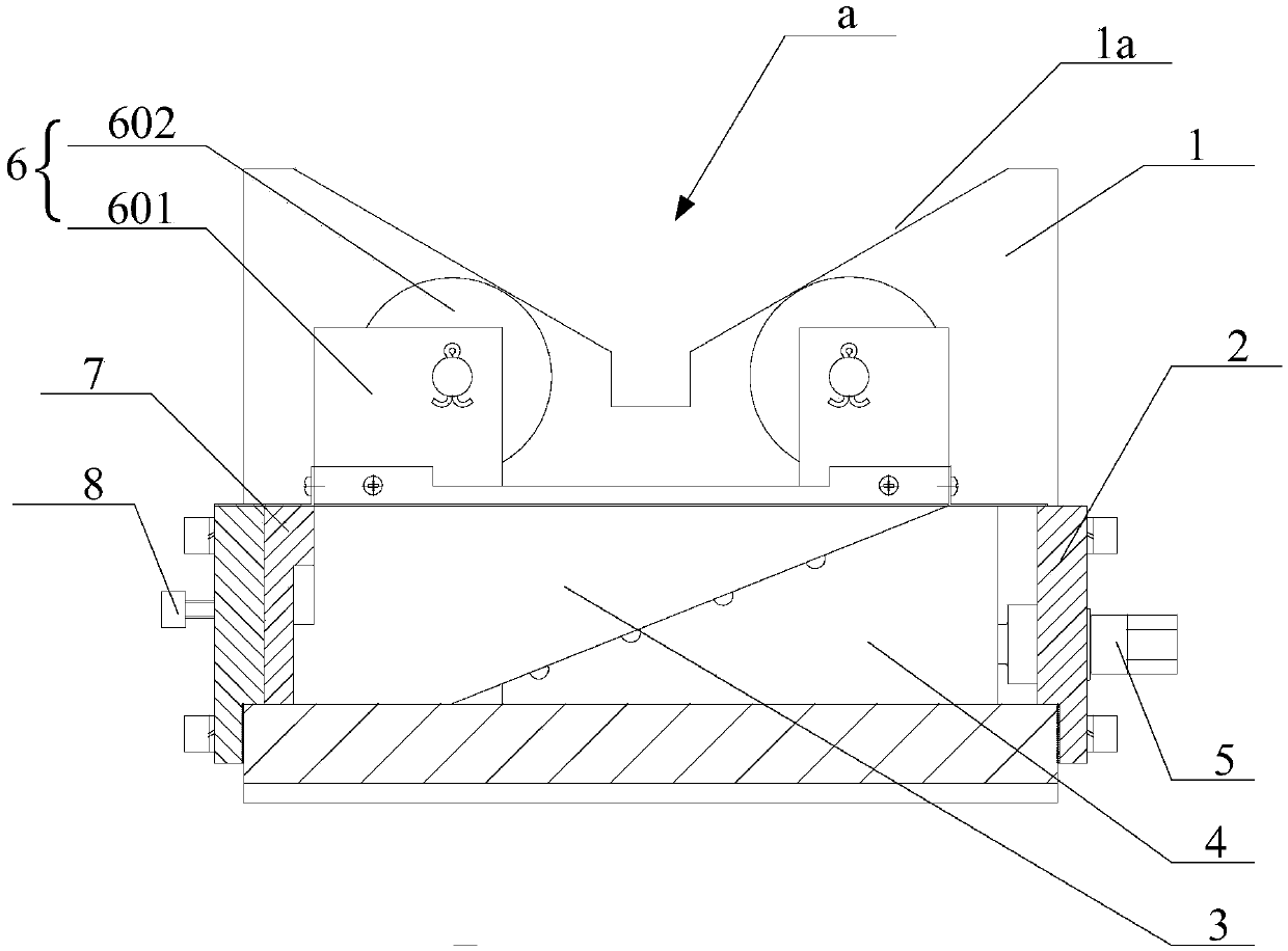
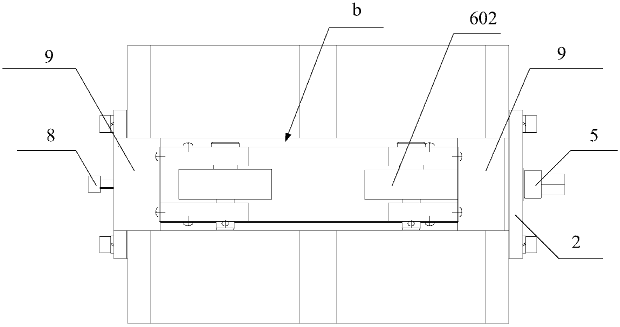
[0022] figure 1 It is a schematic cross-sectional structure diagram of a V-shaped iron provided by the embodiment of the present invention, including a V-shaped iron body 1, and a V-shaped groove a is arranged on the V-shaped iron body 1, and the V-shaped groove a includes two shaft support surfaces 1a , figure 2 It is a top view of the V-shaped iron provided by the embodiment of the present invention, combined with figure 2 , V-shaped groove a is provided with a through groove b perpendicular to the length direction of the V-shaped groove, a cover plate 2 is provided at the openings at both ends of the through groove b, and an upper slider 3 and a sliding slide are arranged in the through groove b. block 4, a screw rod 5 is insert...


PUM


Abstract

The invention discloses V-shaped iron, and relates to the field of mechanical auxiliary tools. The V-shaped iron comprises a V-shaped iron body. The V-shaped iron body is provided with a V-shaped groove. Two shaft supporting surfaces are arranged on the two side walls of the V-shaped groove correspondingly. A through groove is formed in the V-shaped groove. Openings in the two ends of the through groove are provided with cover plates correspondingly. An upper sliding block and a lower sliding block are arranged between the two cover plates. A lead screw is horizontally inserted into one of the cover plates. The lead screw is in threaded connection with the lower sliding block. The lower sliding block and the upper sliding block are provided with oblique planes which are in sliding fit with each other. The other side of the upper sliding block is in sliding fit with the other cover plate. At least one pair of rollers used for supporting shaft parts are arranged at the upper end of the upper sliding block. The lower sliding block can be pushed by rotating the lead screw, displacement in the horizontal direction of the lower sliding block is converted into displacement in the vertical direction of the upper sliding block, and thus the upper sliding block can move upwards. The rollers installed on the upper sliding block stretch out of the two shaft supporting surfaces of the V-shaped groove so that the parts can be jacked up. The parts are supported between the two rollers, and the shaft parts can be rotated easily through the two rollers.

Description

technical field [0001] The invention relates to the field of mechanical auxiliary tools, in particular to a V-shaped iron. Background technique [0002] In the process of machining precision shaft parts, V-shaped irons are usually used to inspect or correct shaft parts. V-shaped irons consist of two pieces. When inspecting or correcting the shaft parts, place the shaft parts in the V-shaped grooves of two V-shaped irons, find the center line of the V-shaped irons through the V-shaped grooves, and then find the shafts placed on the V-shaped irons. The center line where the center of the part is located, rotate the shaft part, and inspect or correct the shaft part from different angles. [0003] Because rotating the shaft parts directly on the V-shaped iron not only requires a huge force, but also easily damages the workpiece or the V-shaped iron during the rotation process, so it is usually necessary to use lifting equipment to cooperate with the workpiece to turn over. Exis...

Claims


Application Information

Patent Timeline
Patent Type & Authority Patents(China)
IPC IPC(8): F16H25/24F16H37/00G01M13/00
CPCF16H25/24F16H37/00G01M13/00
Inventor 郭振强蒋国辉吴金星程文池陈离经鹏飞盛文魏雪宋俊杰赵彬
Owner WUHAN MARINE MACHINERY PLANT
Features
  • R&D
  • Intellectual Property
  • Life Sciences
  • Materials
  • Tech Scout
  • Unparalleled Data Quality
  • Higher Quality Content
  • 60% Fewer Hallucinations
Learn More