Special milling cutter for CNC milling machine

A technology of CNC milling machines and milling cutters, which is applied in the direction of milling cutters, milling machine equipment, manufacturing tools, etc., and can solve the problems of CNC milling machines taking a long time, milling cutters out of reach, repeated troubles, etc.

Active Publication Date: 2018-02-06
浙江海拓环宇传动科技有限公司
View PDF9 Cites 1 Cited by
  • Summary
  • Abstract
  • Description
  • Claims
  • Application Information

AI Technical Summary

Problems solved by technology

[0004] Due to the limited length of the milling cutter and the limited distance that the spindle can move, after the processing of this batch of parts is completed, the milling cutter may not be able to reach some smaller parts, so it is necessary to ask a professional to move the spindle It is very troublesome to restore the position to realize the machining of small parts, and it takes a lot of time to adjust all the CNC milling machines

Method used


Image

  • Special milling cutter for CNC milling machine
  • Special milling cutter for CNC milling machine
  • Special milling cutter for CNC milling machine

Examples


Embodiment 1

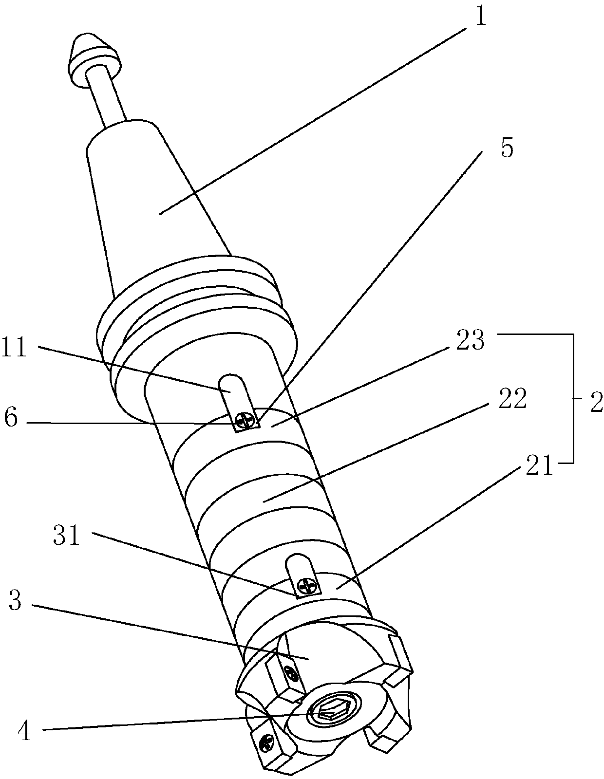
[0024] Embodiment one, such as Figure 1-Figure 2 As shown, a special milling cutter for CNC milling machine includes a tool handle 1 and a cutter head 3. The tool handle 1 adopts the common BT series tool handle 1 on the market, and the cutter head 3 also adopts the existing structure on the market. The overall length of the milling cutter is lengthened by setting the extension section 2 between the shank 1 and the cutter head 3 .

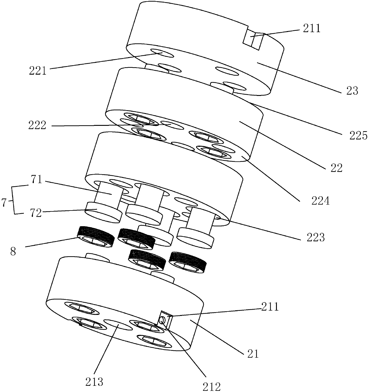
[0025] The elongated section 2 is divided into several independent intermediate units 22, the first section 23 and the end section 21, and the intermediate unit 22, the first section 23 and the end section 21 are all provided with a disc-shaped object with a certain thickness. The thickness can be determined according to specific conditions. The first section 23 is used for connecting the handle 1 , while the last section 21 is used for connecting with the cutter head 3 , and the intermediate unit 22 is located between the first section 23 and the...

Embodiment 2

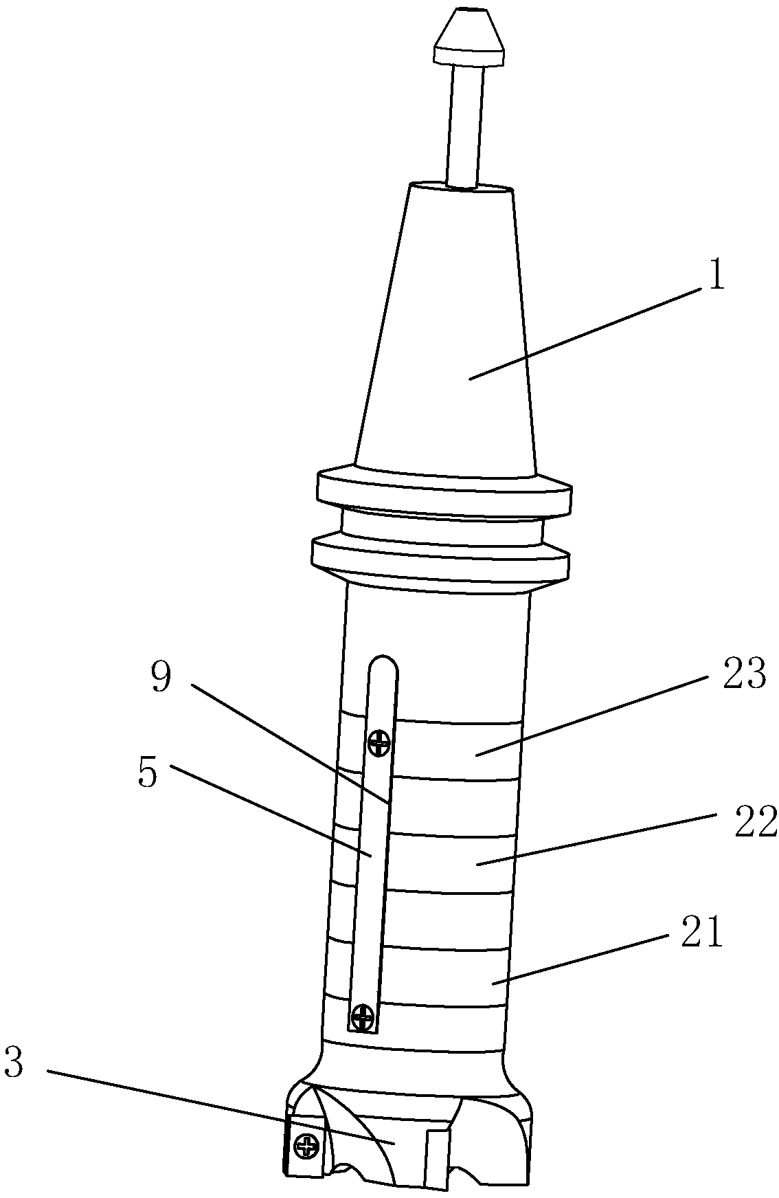
[0030] Embodiment two, such as Figure 4 As shown, the first section 23, the last section 21 and the middle unit 22 are all directly made of magnetic materials, and the magnetic properties of the opposite end faces of the first section 23 and the last section 21 are oppositely set to ensure that the first section 23 and the last section 21 can be connected with the middle unit. The unit 22 forms a magnetic attraction and the connection between the first section 23 and the end section 21 when there is no intermediate unit 22 does not need to set the through hole 222 or the counterbore 223 in the intermediate unit 22, the first section 23 and the end section 21. In the embodiment, the intermediate unit 22 only needs to be provided with two through grooves 9 along the thickness direction on the outer peripheral surface, and the two through grooves 9 are evenly distributed along the circumferential direction. The groove 211 also runs through the first section 23 and the end section...


PUM


Abstract

The invention discloses a milling cutter special for a numerical control milling machine. The milling cutter comprises a cutter handle and a cutter bit. The cutter bit is provided with a connecting groove. A threaded hole is formed in the connecting groove. A clamping connecting groove is formed in the cutter handle. An extension section is arranged between the cutter handle and the cutter bit. The two end portions of the extension section are provided with matching grooves. A connecting block is arranged between the corresponding matching groove and the connecting groove, and a connecting block is arranged between the corresponding matching groove and the clamping connecting groove. The connecting blocks are provided with installation holes matched with the threaded hole. The corresponding connecting block and the cutter handle are connected through a first fastener matched with the threaded hole, and the corresponding connecting block and the cutter bit are connected through a first fastener matched with the threaded hole. The extension section is provided with a center hole used for being connected with the cutter bit. The extension section and the cutter bit are connected by arranging a second fastener matched with the center hole. According to the purpose, the milling cutter special for the numerical control milling machine is provided, it is ensured that small parts can still be machined in the situation that the distance between a main shaft and a clamp is increased by increasing the overall length of the milling cutter, the position of the main shaft does not need to be repeatedly adjusted, the machining process is simplified, and the work efficiency is improved.

Description

technical field [0001] The invention relates to the technical field of CNC milling machine parts, in particular to a special milling cutter for a CNC milling machine. Background technique [0002] CNC milling machine is a necessary processing equipment in modern industrial production, as shown in the accompanying drawings Figure 4 As shown, the CNC milling machine usually includes a processing table 102, on which a clamp 103 for clamping the parts to be processed is arranged, the clamp 103 is positioned on the processing table 102, a spindle 101 is arranged above the clamp 103, and a spindle 101 is arranged on the spindle 101 The corresponding milling cutter is installed, and the distance between the spindle 101 and the clamp 103 determines the size of the part to be processed. [0003] The size of the CNC milling machine is only a few gears, and the CNC milling machines between adjacent gears are very different. Many companies will choose the appropriate size of the CNC mi...

Claims


Application Information

Patent Timeline
Patent Type & Authority Patents(China)
IPC IPC(8): B23C5/10B23C5/16
CPCB23C5/10B23C5/16
Inventor 李默
Owner 浙江海拓环宇传动科技有限公司
Why Eureka
Try Eureka