Motor and camshaft thereof, and manufacturing method for camshaft

a technology of camshaft and motor, which is applied in the direction of valve drives, machines/engines, mechanical equipment, etc., can solve the problems of long time consumption, complicated manufacturing process, and high cost, and achieves simplified manufacturing process, simplified structure, and high torque transmission

Active Publication Date: 2019-07-25
SHANGHAI UNIVERSOON AUTOPARTS CO LTD
View PDF1 Cites 0 Cited by
  • Summary
  • Abstract
  • Description
  • Claims
  • Application Information

AI Technical Summary

Benefits of technology

[0182]Comparing with the prior technologies, technical solution of the present invention has the following advantages:
[0183]In the camshaft according to the present invention, outer circumferential surface of the central shaft fitting section of the camshaft is configured into a polygon, inner circumferential surfaces of the first cam and second cam are also configured into a polygon, the central shaft and the first cam and second cam are subject to force fit between the outer circumferential surface of the polygon and inner circumferential surface of the polygon, whereby a fixed and rotation resisting connection is formed between the two. Compared with the splined connection of prior camshaft, this camshaft has the advantages of higher torque transmission, simpler structure, simplified manufacturing process, shorter manufacturing time consumption and reduced cost.
[0184]Furthermore, the cam includes a first cam and a second cam that are mutually separated and axially spaced on the central shaft, and compared with one-piece cam, axial dimensions of the first cam and second cam are reduced, which can be formed by stamping process at a lower cost.
[0185]Furthermore, axially in the direction towards the second part, dimensions of the cross sectional of the inner circumferential surface of the first part tend to decrease. Axially in the direction towards the first part, dimensions of the cross sectional of the inner circumferential surface of the second part tend to decrease. During expansion, the first part and the second part can be in relative motion so that these two can press tightly against each other axially. During manufacturing, the first part and the second part can, before expansion, be put on the outside of the central shaft and made come into contact with each other axially or have a very small axial clearance there-between, and the relative motion between the first part and the second part during expansion is used to increase the axial pressing force or eliminate the axial clearance, thus, reducing the camshaft manufacturing difficulties.
[0186]In the camshaft, outer circumferential surface profile of the central shaft includes linear zone and circular zone arranged in an interweaved manner, and the linear zone belongs to the same polygon, the circular zone belongs to the same circle. When fitting with the cam, a fixed and rotation resisting connection can be realized between these two through fitting between the circular zone and the cam inner bore. This solution can be used to simplify the structure and manufacturing process of prior camshaft, shorten the time consumed for camshaft manufacturing and reduce the cost, while sufficiently higher torque transmission is guaranteed.
[0187]In the camshaft, the outer circumferential surface profile of the central shaft includes linear zone and circular zone arranged in an interweaved manner, and the linear zone belongs to the same polygon, the circular zone belongs to the same circle. When fitting with the cam, a fixed and rotation resisting connection can be realized between these two through fitting between the circular zone and the cam inner bore. This solution can be used to simplify the structure and manufacturing process of prior camshaft, shorten the time consumed for camshaft manufacturing and reduce the cost, while sufficiently higher torque transmission is guaranteed.

Problems solved by technology

Firstly, in order to form splines on the inner circumferential surface of the cam and the outer circumferential surface of the central shaft, the structure of the parts is made complicated. In addition, a special-purposed machine must be used to form the splines, and the parts are subject to carburization treatment to ensure a good part performance, resulting in complicated manufacturing process, long time consumption and high cost.
Secondly, the cam requires big axial dimensions, which is usually formed by means of casting process at a higher cost.
Thirdly, torque that can be transmitted by the splines is limited.
Camshaft manufactured by casting method and forging method has a plural of demerits, for example, performance maximization design and utilization are impossible in various positions of the camshaft.
If only a single type of material is used, it is impossible to maximize the performance of each part, and the whole manufacturing process is complicated and requires a great number of machining procedures, resulting in a low productivity, high energy consumption and severe environmental pollution.
In addition, a special-purposed machine must be used to form the splines, and the parts are subject to carburization treatment to ensure a good part performance, resulting in complicated manufacturing process, long time consumption and high cost.
Secondly, for the splined connection between the cam and the central shaft, only one cam can be connected on the central shaft at a time, and the assembly of one camshaft can only be completed by multiple sub-assemblies.

Method used


Image

  • Motor and camshaft thereof, and manufacturing method for camshaft
  • Motor and camshaft thereof, and manufacturing method for camshaft
  • Motor and camshaft thereof, and manufacturing method for camshaft

Examples


embodiment 1

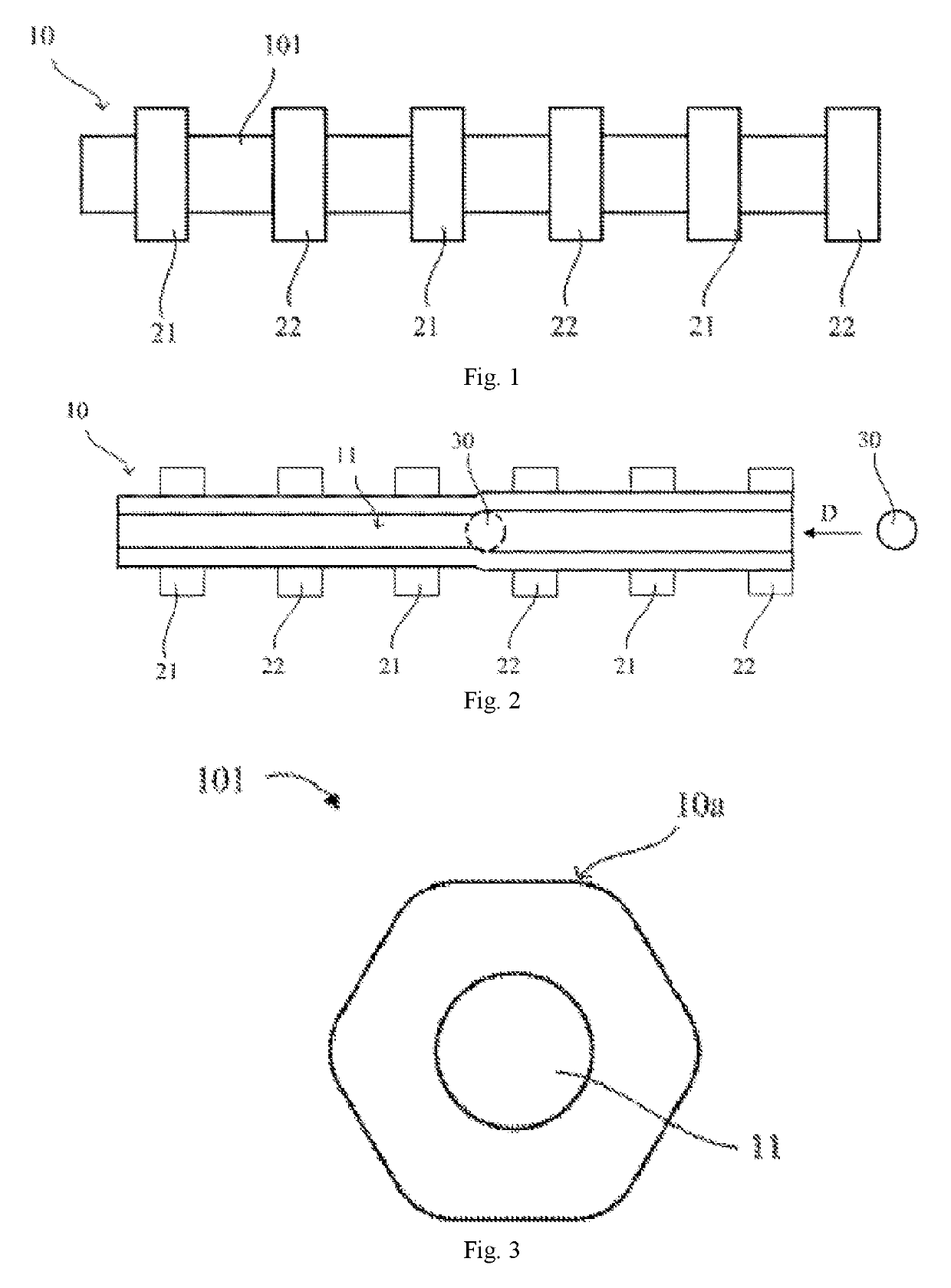
[0212]An embodiment of the present invention provides a camshaft, as shown in FIG. 1, comprising a central shaft 10 and a plural of cams installed on the outside of central shaft 10. The plural of cams include a first cam 21, a second cam 22. The first cam 21 and the second cam 22 are respectively installed on the outside of central shaft 10 and axially spaced.

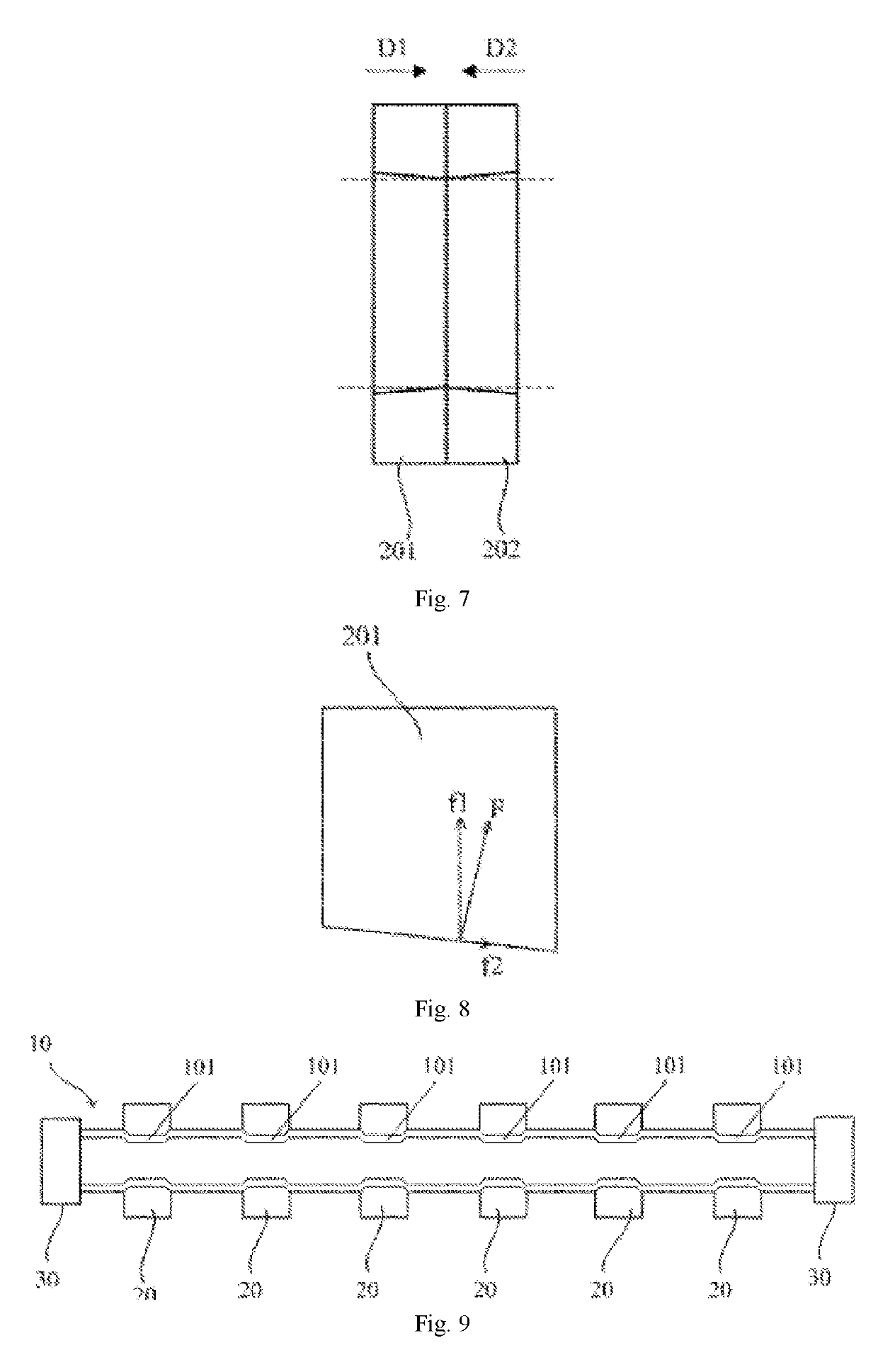
[0213]FIG. 1 exemplarily shows a camshaft having six cams, each cam on the camshaft corresponds with a cylinder, the first cam 21 and the second cam 22 are respectively connected with the central shaft 10 in a rotation resisting manner for synchronous rotation. The first cam 21 and the second cam 22 are respectively used for driving different air valves. In the embodiment illustrated by FIG. 1, the first cam 21 and the second cam 22 are neighboring each other, and there is no other cam between them. In other embodiments, other cams may be provided between the first cam 21 and the second cam 22.

[0214]Central shaft 10 has an axi...

embodiment 2

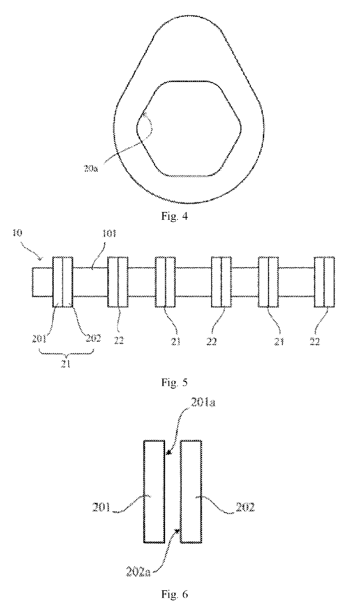
[0222]This embodiment provides a camshaft. In this embodiment, structure of the first cam 21 and the second cam 22 of the camshaft is changed based on Embodiment 1.

[0223]Referring to FIG. 5, at least one of the first cam 21 and the second cam 22 includes an axially spaced first part 201 and second part 202, the first part 201 and the second part 202 are respectively installed on the central shaft 10 and fixed on the central shaft 10 axially, radially and circumferentially, namely, the first part 201 and the second part 202 are totally fixed with the central shaft 10, and after the assembly is completed, they do not engage in any relative motion to the central shaft 10 axially, radially and circumferentially, in which it is also possible to configure in such a manner that all cams installed on the central shaft 10 include the first part and second part; and it is also possible to configure in such a manner that part of the cams installed on the central shaft 10 include the first part...

embodiment 3

[0237]This embodiment provides an engine, including the camshaft mentioned in the above Embodiment 1 and Embodiment 2, as well as a first air valve, a second air valve, wherein, the first cam 21 is used for driving the first air valve but do not drive the second air valve, the second cam 22 is used for driving the second air valve but do not drive the first air valve.

[0238]The first air valve and the second air valve may be respectively the air valves of the same cylinder, or may be air valves of different cylinders.

[0239]When the cam includes a first part 201 and a second part 202, the first part 201 and the second part 202 of the same cam drive at least the same air valve.


PUM

PropertyMeasurementUnit
diameteraaaaaaaaaa
shapeaaaaaaaaaa
outer diametersaaaaaaaaaa

Abstract

Engine and its camshaft, camshaft manufacturing method, the camshaft comprises a central shaft having an axial hole, the central shaft has a fitting section, the outer circumference of a cross section at any axial position of the fitting section is a polygon; a first cam and a second cam, the first cam and second cam are respectively installed on the fitting section of the central shaft and are spaced axially. Such a structure has the advantages of higher torque transmission, simpler structure, simplified manufacturing process, shorter manufacturing time consumption and reduced cost.

Description

[0001]This application claims priority to Chinese Patent Application No. 201610537009.5, entitled “Engine, camshaft thereof, camshaft manufacturing method” filed on Jun. 8, 2016; Chinese Patent Application No. 201610899486.6, entitled” Camshaft and camshaft tube and cam manufacturing method” filed on Oct. 14, 2016; and Chinese Patent Application No. 201710387766.3, entitled “Camshaft and Camshaft Manufacturing Method” filed on May 26, 2017, all of which are incorporated herein by reference.TECHNICAL FIELD[0002]The present invention relates to the automobile engine field, and more particularly to an engine and engine camshaft, camshaft manufacturing method.BACKGROUND[0003]The valve mechanism of an engine is responsible for providing fresh air for the engine cylinders, which is required for gasoline combustion and doing work, and for exhaust emission.[0004]Camshafts are critical components of the valve mechanism. An engine is equipped with an admission camshaft and an emission camshaf...

Claims


Application Information

Patent Timeline
Patent Type & Authority Applications(United States)
IPC IPC(8): F16H53/02F01L1/047B21C1/22B21K1/06
CPCF16H53/025F01L1/047B21C1/22B21K1/06F01L2001/0475F01L2001/0473F01L2103/00F01L2001/0471F01L2001/0476F01L1/08F01L2303/00
Inventor XI, YONGYANG, ZHOUZHU, SONGZHANG, FENGWU
Owner SHANGHAI UNIVERSOON AUTOPARTS CO LTD
Why Eureka
Try Eureka