Gear rack drive revolving worktable

A technology of rotary table and rack and pinion, which is applied in the direction of manufacturing tools, metal processing equipment, metal processing machinery parts, etc., can solve the problems of not applying high-precision rotary table, transmission torque limit, etc., and achieve simple structure, eliminate Clearance, reliable effect

Inactive Publication Date: 2015-09-30
HUBEI UNIV OF AUTOMOTIVE TECH
View PDF12 Cites 9 Cited by
  • Summary
  • Abstract
  • Description
  • Claims
  • Application Information

AI Technical Summary

Problems solved by technology

Although this method can automatically eliminate the backlash, since the transmission torque is limited by the spring tension, this kind of anti-backlash mechanism can only be used in occasions where the transmission load is small, and has not yet been applied to high-precision rotary tables.

Method used


Image

  • Gear rack drive revolving worktable
  • Gear rack drive revolving worktable
  • Gear rack drive revolving worktable

Examples


Embodiment Construction

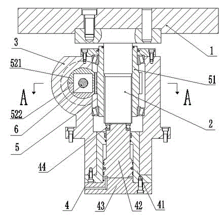
[0044] Such as Figure 1 to Figure 5 As shown, the rack and pinion drive rotary table of the present invention is hydraulically driven, and includes the table 1, the box body 3, the lifting drive mechanism 4, the rotary drive mechanism 5 and the anti-backlash mechanism 6; wherein the table 1 passes through the spline shaft 2 is assembled and connected to the box body 3, and is supported and limited by the spline shaft 2, and the worktable 1 is fixedly connected to the spline shaft 2 by screws; the rotary drive mechanism 4, the lift drive mechanism 5 and the anti-backlash mechanism 6 are installed in Inside the box 3, the rotary drive mechanism 3 and the lift drive mechanism 4 are respectively assembled and connected with the spline shaft 2 and drive the spline shaft 2;

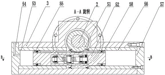
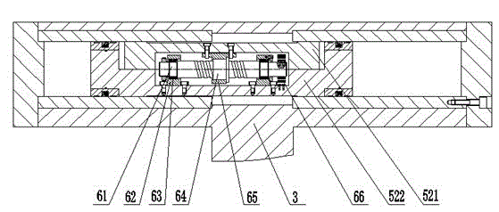
[0045] Figure 1 to Figure 5 in, figure 1 Shows the lifting drive mechanism of the rack and pinion drive rotary table and the installation relationship of the various parts in the box; figure 2 Shows the rotary d...


PUM


Abstract

The invention relates to a gear rack drive revolving worktable. The gear rack drive revolving worktable comprises a working table, a box, a lifting driving mechanism, a revolving driving mechanism and a gap eliminating mechanism, wherein the revolving driving mechanism is driven by a gear and a rack; the rack is formed by laminating two racks; and the gap eliminating mechanism comprises a lead screw shaft, a bearing bracket, a rolling needle bearing, a nut, a nut bracket and a plane scroll spring placed in a cavity formed in the two racks. The revolving worktable is driven by a hydraulic cylinder, can realize 180 degrees of fixed-angle transposition, can automatically eliminate the gap, and is large in transfer torque, simple in structure and reliable in operation.

Description

Technical field [0001] The invention belongs to the technical field of machine tool equipment, and relates to a rotary table of a numerically controlled machine tool, in particular to a rotary table driven by a rack and pinion capable of automatically eliminating tooth side clearance. Background technique [0002] The high-precision rotary table is one of the indispensable parts of CNC machine tools. In some cases, a 180-degree fixed-angle rotary table is required. To achieve fixed-angle indexing, it is better to use hydraulic cylinder drive and rack-and-pinion drive. However, rack-and-pinion transmission often has tooth side clearance, which requires that the rack-and-pinion transmission mechanism must take measures to eliminate the tooth side clearance to ensure the two-way transmission accuracy of the mechanism. Therefore, for high-precision machine tools, eliminating the gap of the rack and pinion mechanism becomes particularly important. [0003] At present, the method usual...

Claims


Application Information

Patent Timeline
Patent Type & Authority Applications(China)
IPC IPC(8): B23Q1/26
CPCB23Q1/26
Inventor 邱新桥吴家浩
Owner HUBEI UNIV OF AUTOMOTIVE TECH
Why Eureka
Try Eureka