Damping device for dynamoelectric precision transmission system

A technology of precision transmission and damping device, applied in the direction of transmission device, mechanical equipment, belt/chain/gear, etc., can solve the problems of destroying the movement mode and movement accuracy of the system, complex structure and assembly, and inability to overcome interference, and achieve a simple structure. , fast response time, improve the effect of transmission efficiency

Inactive Publication Date: 2009-02-11
CHONGQING UNIV
View PDF0 Cites 4 Cited by
  • Summary
  • Abstract
  • Description
  • Claims
  • Application Information

AI Technical Summary

Problems solved by technology

In the prior art, there are various structures for reducing the meshing clearance of the gear pair, but these prior art still have complex structure and assembly in terms of structural design or manufacturing process, and the cost is high, which cannot completely solve the hysteresis of the gear transmission. question
In particular, it cannot overcome the interference outside the system. When an external additional torque is applied to the output of the system, it will destroy the motion mode and motion accuracy of the system.

Method used


Image

  • Damping device for dynamoelectric precision transmission system
  • Damping device for dynamoelectric precision transmission system
  • Damping device for dynamoelectric precision transmission system

Examples


Embodiment Construction

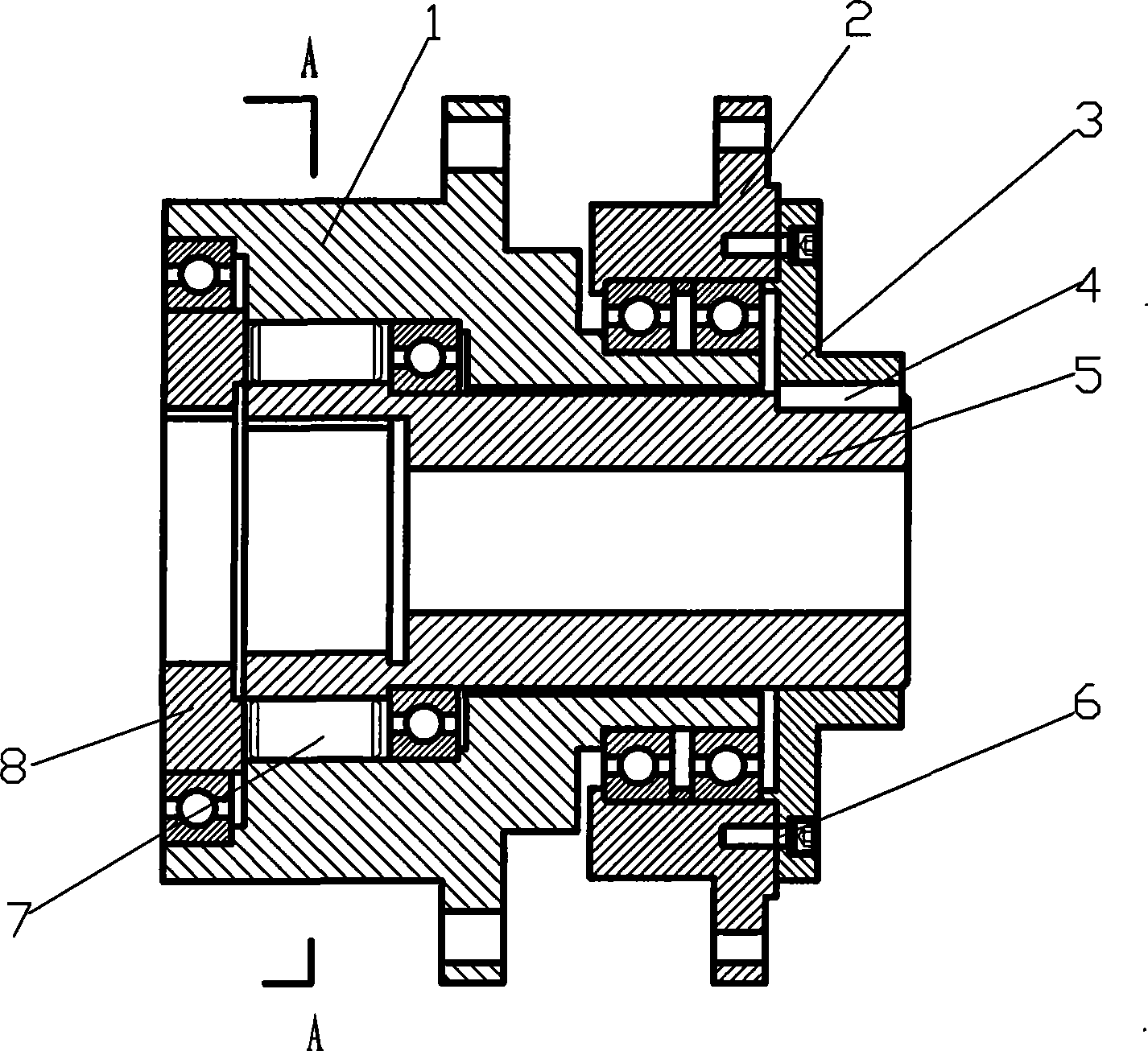
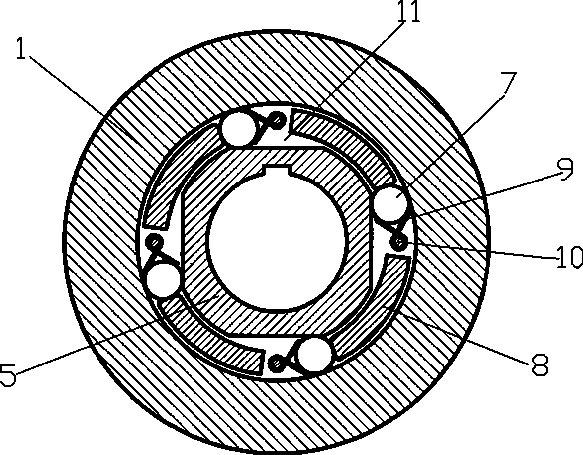
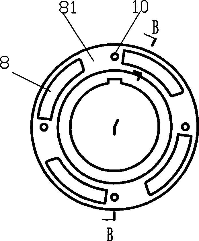
[0023] figure 1 It is a structural schematic diagram of the present invention, figure 2 for figure 1 Along the schematic diagram of A-A, image 3 It is a schematic diagram of the retaining ring structure of the present invention, Figure 4 for image 3 Schematic diagram along the B-B direction, as shown in the figure: the electromechanical precision transmission system damping device of this embodiment includes a fixed ring 1, a power output shaft 5 and a retaining ring 8, and the power output shaft 5 is an axial hollow structure with light weight , is suitable for precision transmission; the fixed ring 1 is arranged on the outer circumference of the power output shaft 5, the power output shaft 5 and the fixed ring 1 are rotated and matched through rolling bearings, and the retaining ring 8 is arranged between the power output shaft 5 and the fixed ring 1 with a clearance fit, maintaining The ring 8 and the fixed ring are rotatably matched by rolling bearings, and at leas...


PUM


Abstract

The invention discloses a damping device of an electromechanical precision drive system, comprising a fixing ring, a power output shaft and a retaining ring; the power output shaft is in running fit with the fixing ring, the retaining ring is arranged between the power output shaft and the fixing ring in a clearance fit way, a wedge groove is arranged between the power output shaft and the fixing ring and is internally provided with a damping rolling element and an elastic element, the radial size of the narrow end of the wedge groove is smaller than the diameter of the damping rolling element, one end of the retaining ring is provided with an axial open slot corresponding to the wedge groove, the damping rolling element is arranged at the narrow end of the wedge groove, the pre-tightening force direction of the elastic element is opposite to the rotating direction of the power output shaft, the power output shaft and the retaining ring are driven by a power input device to do synchronous rotation; the damping device can use self locking to overcome the interference from environment and other factors, has high driving precision, and can eliminate driving return difference to the utmost extent; furthermore, the device has no interference when running, thus being suitable for an occasion requiring high driving precision; moreover, the damping device can improve driving efficiency, reduce vibration and noise and prolong the service life of the drive system.

Description

technical field [0001] The invention relates to an electromechanical precision transmission device, in particular to a damping device for an electromechanical precision transmission system. Background technique [0002] Electromechanical precision transmission is widely used in various machines and instruments. With the development of production technology and the demand for high-quality products, especially the development needs of precision testing, processing and manufacturing, national defense, aerospace, etc., the transmission accuracy and backlash, that is, the tooth side Gap control puts forward higher requirements. [0003] In order to eliminate the meshing gap and motion hysteresis of gear pairs in precision transmission, damping devices are widely used. In the prior art, there are various structures for reducing the meshing clearance of the gear pair, but these prior art still have complex structure and assembly in terms of structural design or manufacturing proce...

Claims


Application Information

Patent Timeline
Patent Type & Authority Applications(China)
IPC IPC(8): F16H35/00
Inventor 陈小安
Owner CHONGQING UNIV
Why Eureka
Try Eureka