Solar energy power machine

A power machine and solar energy technology, which is applied in the direction of generating mechanical power with solar energy, solar thermal power generation, and mechanisms for generating mechanical power. The effect of less transmission clearance and simple transmission structure

Inactive Publication Date: 2019-01-15
CHANGZHOU INST OF MECHATRONIC TECH
View PDF6 Cites 3 Cited by
  • Summary
  • Abstract
  • Description
  • Claims
  • Application Information

AI Technical Summary

Problems solved by technology

More transmission links will lead to more transmission gaps, which will consume the slight expansion and contraction deformation of the heat-bearing thin plate, so the energy conversion efficiency of the power machine will be reduced

Method used


Image

  • Solar energy power machine
  • Solar energy power machine
  • Solar energy power machine

Examples


Embodiment 1

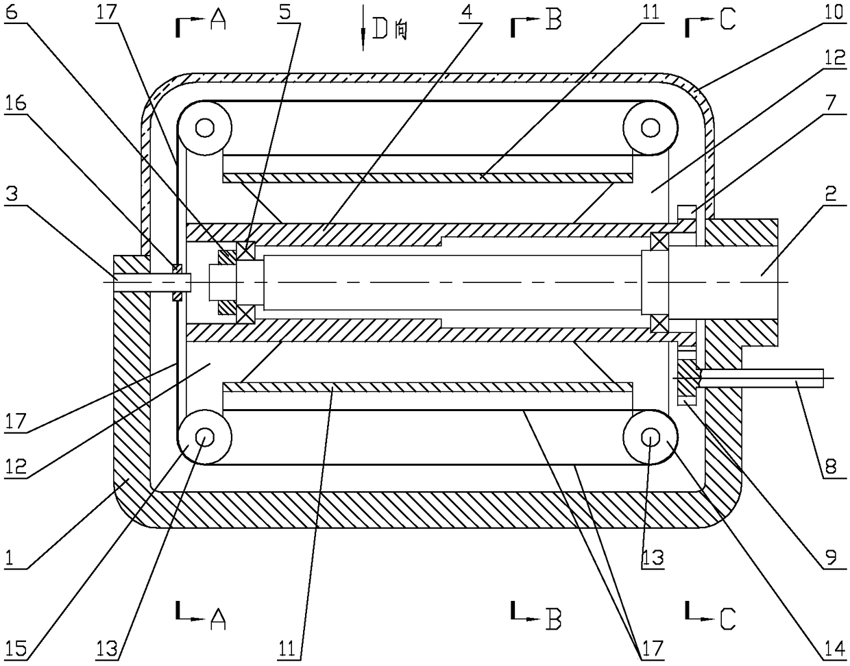
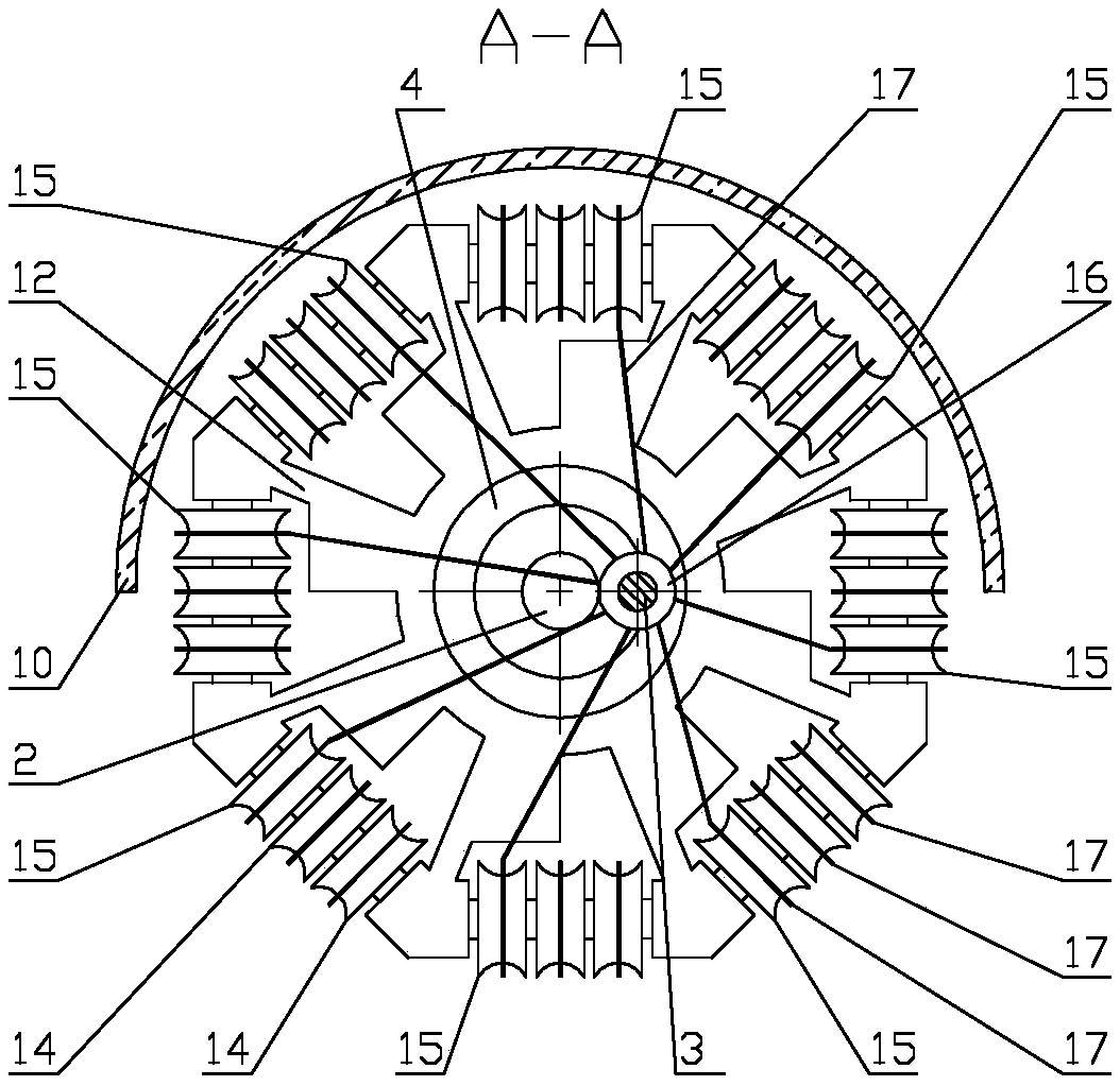
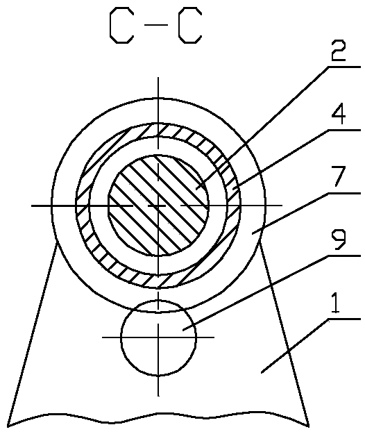
[0030] see figure 1 , figure 2 , image 3 , Figure 4 , Figure 5 , the solar power machine described in the present embodiment includes: frame 1, main shaft 2, support shaft 3, rotating drum 4, bearing 5, nut 6, bull gear 7, output shaft 8, pinion 9, telescopic mechanism and exposure Type heat collecting cover 10.

[0031] see figure 1 , on the opposite two walls of the open frame 1, the main shaft 2 and the support shaft 3 are respectively provided in the form of a cantilever, and the free end of the main shaft 2 is opposite to the free end of the support shaft 3. The frame 1 of the embodiment is U-shaped, and the main shaft 2 and the supporting shaft 3 are respectively arranged on two opposite walls of the U-shaped frame 1 in the form of a cantilever. The form that the main shaft 2 is located on the frame 1 is preferably fixed. see figure 2 , the axis of the support shaft 3 is parallel to and staggered with the axis of the main shaft 2, the axis of the support shaf...

Embodiment 2

[0047] In order to improve the power output of the solar power machine, on the basis of the solar power machine described in embodiment 1, a steering mechanism is also added, please refer to Figure 7 , Figure 8 , Steering mechanism includes: steering shaft 19 and bogie frame 20.

[0048] see Figure 7 , Figure 8 , the steering shaft 19 is fixed on the frame 1 and the steering shaft 19 is coaxial with the output shaft 8, the steering shaft 19 is suitable for connecting to an external servo drive device, and the steering frame 20 is provided with a supporting On the base of the ground, the bogie frame 20 is respectively provided with holes that are pivotally hinged with the output shaft 8 and pivotally hinged with the steering shaft 19 .

[0049] The working principle and beneficial effects of the steering mechanism: see Figure 7 , Figure 8 , in order to make the solar power machine of the present invention maintain a higher power output, the heat collecting cover 10 o...


PUM


Abstract

The invention relates to a solar energy power machine. The solar energy power machine includes a frame, a main shaft and a supporting shaft which are arranged on the frame in a cantilever mode, a rotation cylinder rotatably supported on the main shaft, a large gear arranged on the rotation cylinder, an output shaft rotatably supported on the frame, a small gear arranged on the output shaft, an open-ended heat collecting cover made of a light-transmitting material and a telescopic mechanism, wherein a suspension end of the main shaft and a suspension end of the supporting shaft are opposite, the axis of the supporting shaft and the axis of the main shaft are staggered and in parallel, the small gear and the large gear are engaged, the telescopic mechanism includes a pulley frame mounted attwo ends of the rotation cylinder, and a pulley and a tail pulley rotatably supported on the pulley frame through a pulley shaft, a bearing ring rotatably supported on the supporting shaft, and an elastic filament which bypasses the pulley and the tail pulley, and two ends of the elastic filament are respectively connected with the pulley frame and the bearing ring. The solar energy power machinehas advantages of simple transmission structure and small quantity of transmission gaps.

Description

technical field [0001] The invention relates to the technical field of solar power machines, in particular to a power machine that utilizes solar heat radiation to directly generate mechanical energy. Background technique [0002] Solar energy is the cleanest and inexhaustible source of energy. It is very meaningful to use solar energy to directly generate mechanical energy. For example, using solar energy to directly generate mechanical energy to drive water pumps for water conservancy irrigation. [0003] The utility model patent with the patent application number CN96240203.6 discloses a plate-type sunlight and small temperature difference thermal radiation power machine, which provides a technical solution for directly generating mechanical energy by utilizing solar energy. The technical solution of this utility model patent is: a crankshaft or camshaft group with a combination of main shaft gear and eccentric shaft gear. The eccentric shaft gear is positioned by the fr...

Claims


Application Information

Patent Timeline
Patent Type & Authority Applications(China)
IPC IPC(8): F03G6/06F03G7/06
CPCF03G6/06F03G7/06Y02E10/46
Inventor 高志坚王琳杨兰赵海姜海军庞雨花
Owner CHANGZHOU INST OF MECHATRONIC TECH
Why Eureka
Try Eureka