
Metal V-belt of continuously variable transmission

a technology of continuously variable transmission and v-belt, which is applied in the direction of v-belts, driving belts, belts/chains/gearrings, etc., can solve the problems of excessive bearing pressure, undesirable phenomena, and failure to exhibit satisfied contact characteristics of the flank surface with the conical faces of the drive and the driven pulley, etc., to achieve high torque transmission and long use of the transmission

Active Publication Date: 2014-08-26
JATCO LTD
View PDF29 Cites 9 Cited by
  • Summary
  • Abstract
  • Description
  • Claims
  • Application Information

AI Technical Summary

Benefits of technology

The present invention provides a metal V-belt for continuously variable transmissions that overcomes the problem of premature wear and tear. This is achieved by improving the contact area between the belt and pulley, ensuring a long usage of the transmission with high torque capacity.

Problems solved by technology

However, in the above-mentioned V-belts hitherto proposed, due to the nature of the fine grooves formed on the flank surface of the steel element, the frictional contact of the flank surface with the conical faces of the drive and driven pulleys fails to exhibit satisfied contact characteristics.
Measuring a bearing pressure distribution of the flank surface having such area ratio has revealed that a middle portion of each raised portion is subjected to an excessively high bearing pressure, which is of course undesirable.
Furthermore, if the above-mentioned V-belts are employed in a heavy duty continuously variable transmission without making suitable improvement to the V-belt or to the pulleys, undesirable phenomena tend to occur, which are, for example, remarkable abrasion of the flank surfaces of the steel elements.
As is known, when the flank surface is remarkably abraded, the fine grooves of the flank surface reduce their oil holding capacity, which deteriorates the lubrication oil discharging effect.
Thus, if, due to a partial concentration of bearing pressure, the flank surfaces of the steel elements are subjected a marked bearing pressure thereby producing an excessive shearing force, the protecting film is damaged, which causes failure of producing a desired frictional force.

Method used


Image

  • Metal V-belt of continuously variable transmission
  • Metal V-belt of continuously variable transmission
  • Metal V-belt of continuously variable transmission

Examples


Embodiment Construction

[0041]In the following, a metal V-belt of a continuously variable transmission according to the present invention will be described in detail with reference to the accompanying drawings.

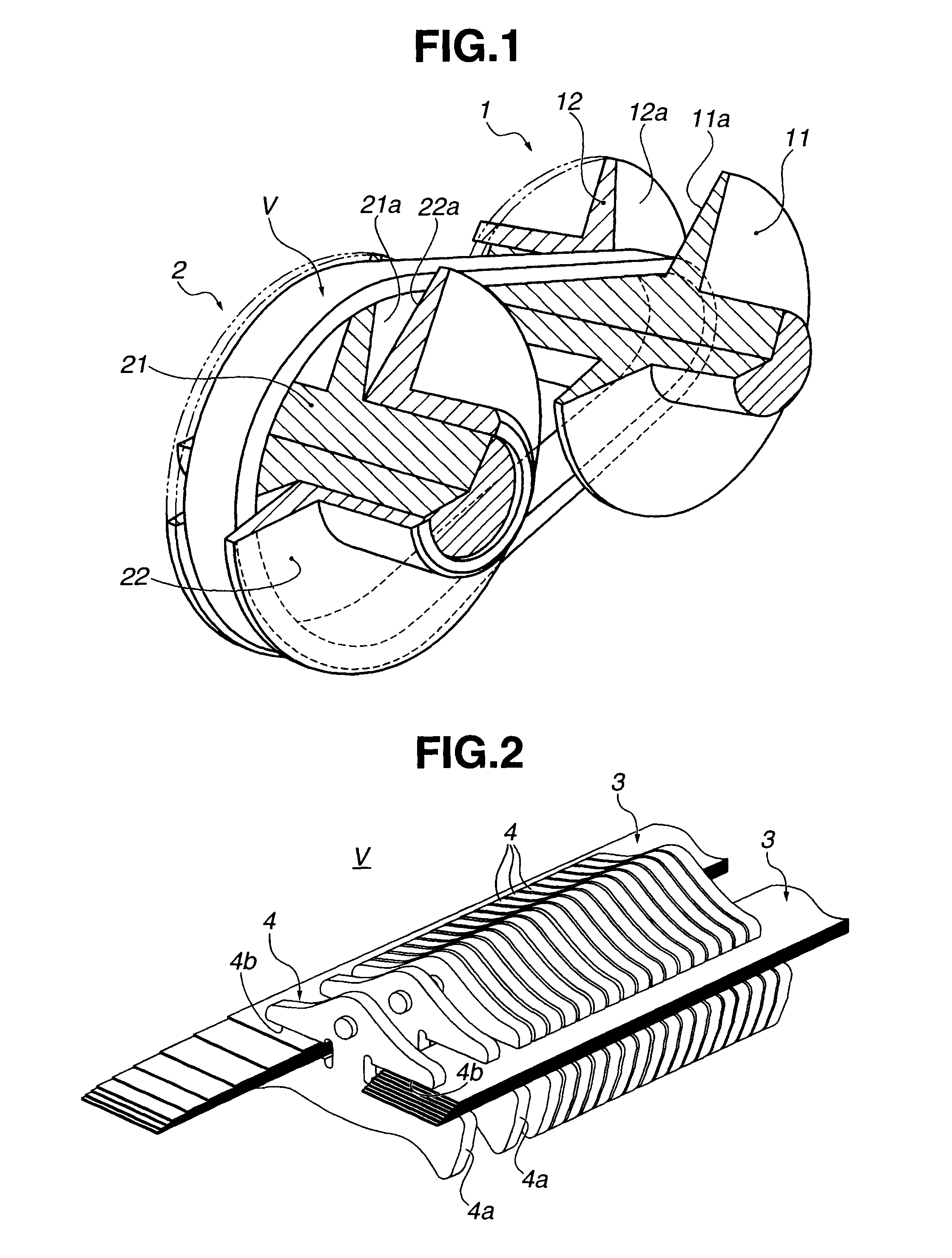
[0042]Referring to FIG. 1, there is schematically shown a continuously variable transmission to which a metal V-belt “V” of the present invention is practically applied.

[0043]The transmission comprises a drive pulley 1 and a driven pulley 2 around which the metal V-belt “V” is practically put.

[0044]Under operation of an associated engine (not shown), an engine torque from a prime mover, such as internal combustion engine or the like is transmitted to the drive pulley 1 through both a torque converter (not shown) and a forward / backward movement switching mechanism (not shown). The engine torque is then transmitted through the V-belt “V” to the driven pulley 2 and then transmitted to drive road wheels (not shown) through both a reduction gear (not shown) and a drive shaft (not shown).

[0045]As shown in ...


PUM


Abstract

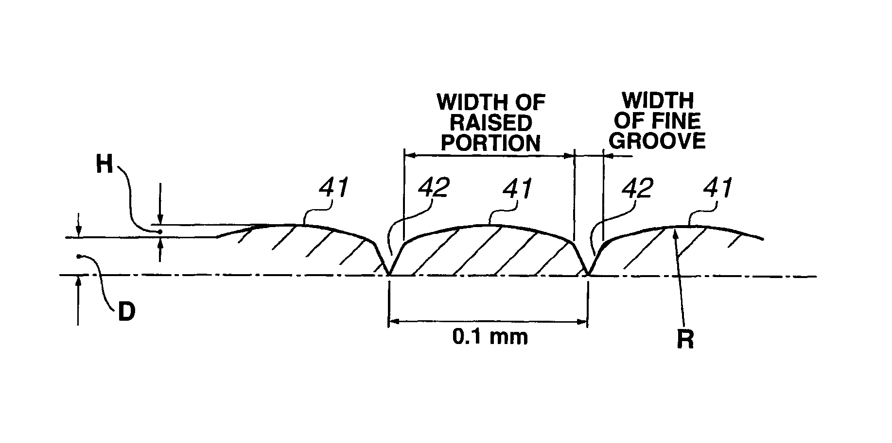
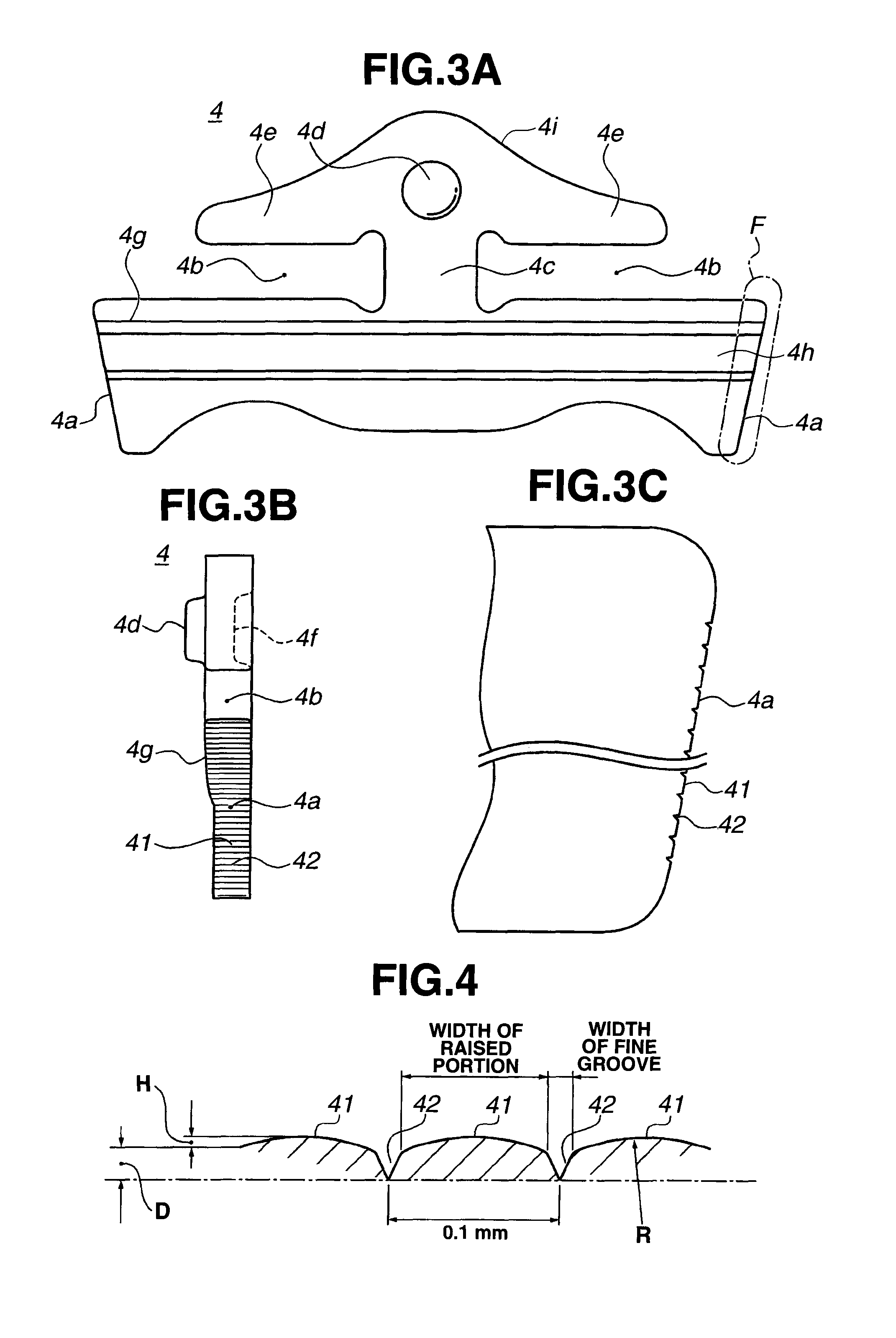
Each steel element for a V-belt of a continuously variable transmission has a flank (4a) that comprises a plurality of equally spaced raised portions (41) each being placed between two fine grooves (42). A flat flatness ratio (FR) given by the equation (1) is set to the highest one of values that are capable of practically machining the flank (4a) of the steel element (4) and capable of causing the flank (4a) to exhibit a given and satisfied lubrication oil discharging effect, and a groove pitch (GP) that is a distance between the two fine grooves (42) is set to a value that is capable of practically machining the flank of the steel element and capable of causing the flank to exhibit a given and satisfied lubrication oil discharging effect. The groove pitch thus set is a value that is permitted by the higher value of the flatness ratio thus set.FR (%)=WRP / (WRP+WG)×100  (1)wherein:FR: Flatness ratioWRP: Width of the raised portion (41)WG: Width of the groove (42).

Description

BACKGROUND OF THE INVENTION[0001]1. Field of the Invention[0002]The present invention relates in general to a belt-type continuously variable transmissions, and more particularly to metal V-belts used by such continuously variable transmissions. More specifically, the present invention is concerned with improvements through which a torque transmission efficiency of the belt is increased.[0003]2. Description of the Related Art[0004]Hitherto, various metal V-belts have been proposed and put into practical use in the field of wheeled motor vehicles that employ the belt-type continuously variable transmissions.[0005]One of them is the metal V-belt disclosed in Japanese Laid-open Patent Application (tokkaihei) 10-213185. The metal V-belt disclosed in this published Application comprises a plurality of steel elements attached consecutively to two laminated steel bands. For such consecutive attaching, the steel elements have opposed grooves (or saddle grooves) that receive inside portions ...

Claims


Application Information

Patent Timeline
Patent Type & Authority Patents(United States)
IPC IPC(8): F16G1/21F16G5/16F16G1/22
CPCF16G5/16F16G5/00F16G9/00
Inventor TOYOHARA, KOUHEIMIZUMIYA, KAZUHIROMIURA, YOSHITAKAKAMITANI, TSUTOMUKIYOHARA, SHINJI
Owner JATCO LTD
Learn More