Gas sensor

a technology of gas sensor and reference electrode, which is applied in the field of gas sensor, can solve the problems of deterioration of reference electrode, affecting the detection accuracy of specific gas concentration, etc., and achieves the effect of further suppressing the change of reference potential in long time us

Active Publication Date: 2015-10-01
NGK INSULATORS LTD
View PDF5 Cites 40 Cited by
  • Summary
  • Abstract
  • Description
  • Claims
  • Application Information

AI Technical Summary

Benefits of technology

[0013]In the gas sensor of the above aspect, the average current density may be not higher than 170 μA/mm2. This enhances the effect of further suppressing a change of the reference potential in long time use.
[0014]In the gas sensor of the above aspect, an average value of the control current may be higher than 1 μA. It is thus unlikely that the effect of compensating for reduction of an oxygen concentration in the periphery of the reference electrode is insufficient.
[0015]In the gas sensor of the above aspect, the measurement-object gas side electrode may be provided on an outer surface of the layered body. For example, when the measurement-object gas side electrode is provided inside of the measurement-object gas flowing portion, oxygen in the measurement-object gas flowing portion is pumped into the reference electrode side. This may affect the detection accuracy. Providing the measurement-o

Problems solved by technology

This may temporarily decrease an oxygen concentration of the reference gas in the periphery of the reference electrode 342 and may thus affect the d

Method used


Image

  • Gas sensor
  • Gas sensor
  • Gas sensor

Examples


experimental example 1

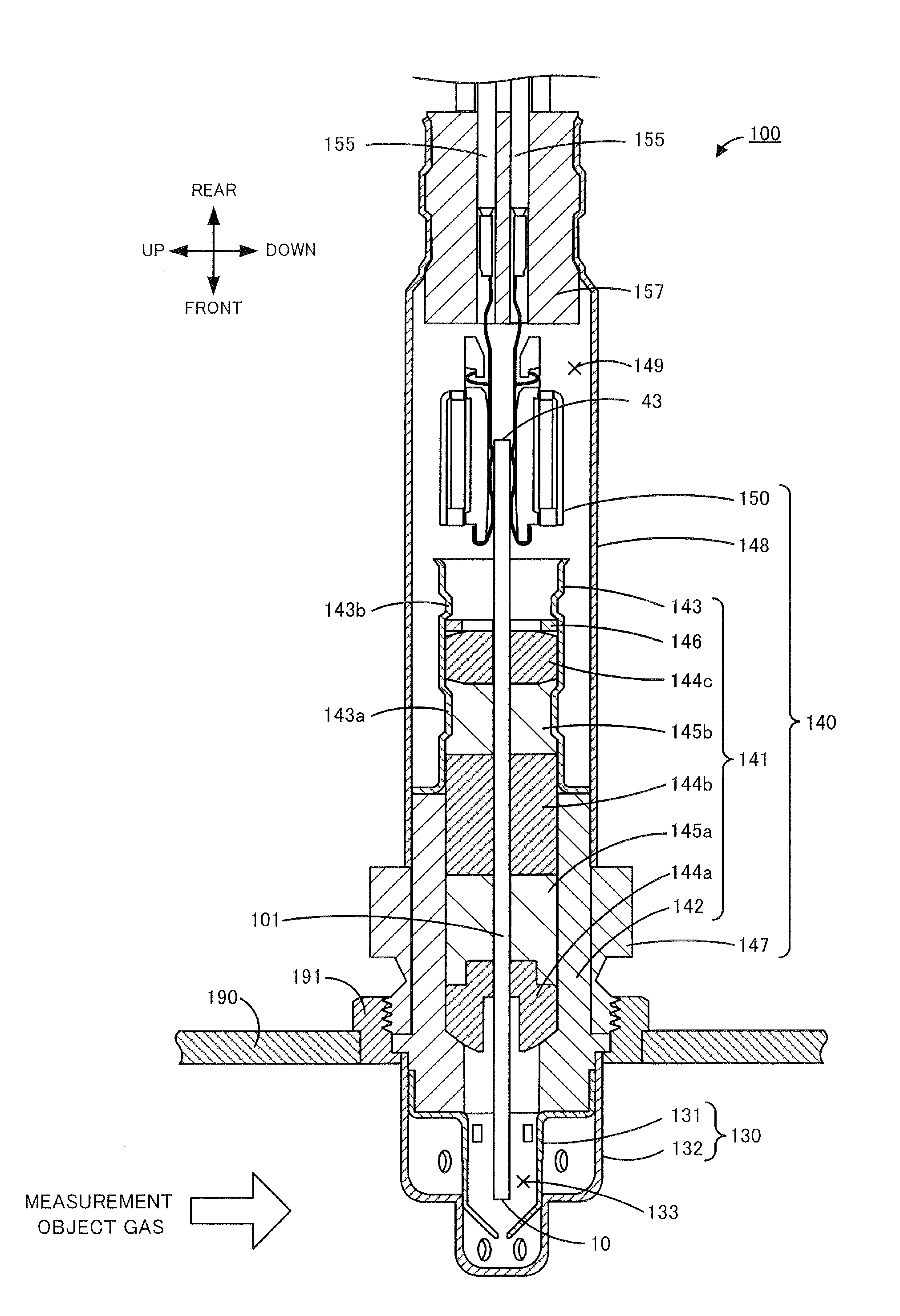
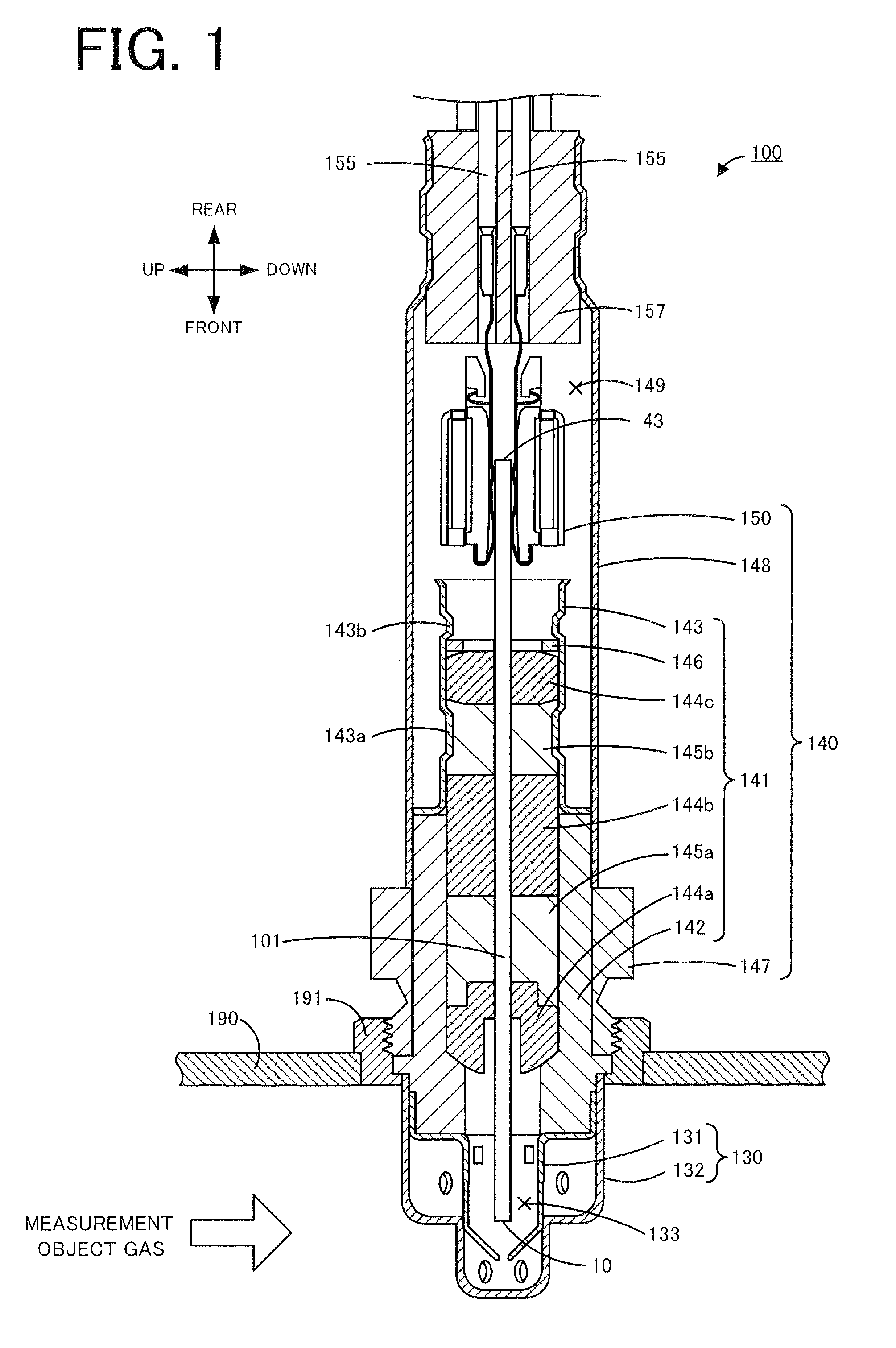
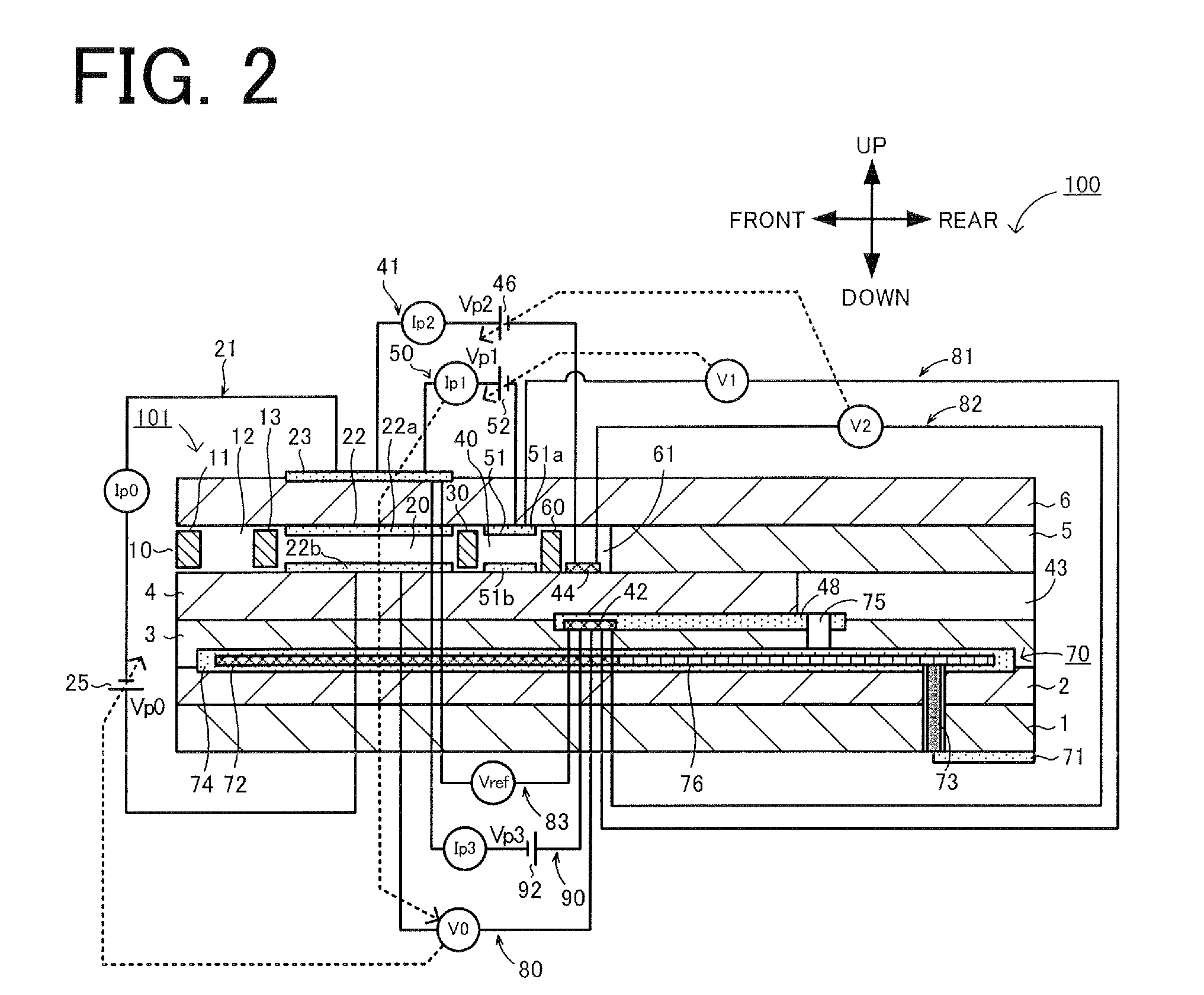
[0088]The gas sensor 100 shown in FIGS. 1 and 2 was produced by the manufacturing procedure described above as Experimental Example 1. The ceramic green sheets used for production of the sensor element 101 were formed by tape casting of a mixture of zirconia particles containing 4 mol % yttria as a stabilizing agent with an organic binder and an organic solvent. The green compacts 145a and 145b shown in FIG. 1 were compacted talc powder. The area S of the reference electrode 42 was 0.6 mm2. Experimental Example 1 did not include the variable power supply 92 and had the control current Ip3 of 0 μA. The average current density of the reference electrode 42 of Experimental Example 1 was accordingly 0 μA / mm2.

experimental example 2

[0089]A gas sensor of Experimental Example 2 was produced in the same manner as Experimental Example 1, except that Experimental Example 2 included the variable power supply 92 and regulated the voltage Vp3 to set the control current Ip3 to do current of 4 μA. The average current density of the reference electrode 42 of Experimental Example 2 was 6.7 μA / mm2.

experimental example 3

[0090]A gas sensor of Experimental Example 3 was produced in the same manner as Experimental Example 1, except that Experimental Example 3 included the variable power supply 92 and regulated the voltage Vp3 to set the control current Ip3 to do current of 8 μA. The average current density of the reference electrode 42 of Experimental Example 3 was 13 μA / mm2.


PUM


Abstract

In a sensor element 101, a reference gas regulation pump cell 90 pumps in oxygen to the periphery of a reference electrode 42 in which a reference gas is introduced, by the flow of a control current Ip3 between the reference electrode 42 and an outer pump electrode 23 located in a region exposed to a measurement-object gas. An average current density of the reference electrode 42 under the flow of this control current Ip3 is higher than 0 μA/mm2 and lower than 400 μA/mm2. The average current density is preferably not higher than 170 μA/mm2. An average value of the control current Ip3 is preferably higher than 1 μA. The outer pump electrode 23 as a measurement-object gas side electrode of the reference gas regulation pump cell 90 may be provided on an outer surface of a layered body (or more specifically, on a second solid electrolyte layer 6).

Description

BACKGROUND OF THE INVENTION[0001]1. Field of the Invention[0002]The present invention relates to a gas sensor.[0003]2. Description of the Related Art[0004]A conventionally known gas sensor detects a specific gas concentration such as NOx in a gas to be measured or a measurement-object gas such as an exhaust gas of an automobile. For example, JP 3798412B and JP 2011-102797A describe gas sensors, each including a sensor element of a long plate-like shape formed by stacking a plurality of airtight oxygen ion-conductive solid electrolyte layers.[0005]FIG. 6 is a sectional schematic diagram schematically illustrating one exemplary configuration of a prior art gas sensor300. As illustrated, this gas sensor 300 includes a sensor element 307. The sensor element 307 is provided as an element of stacked structure by stacking oxygen ion-conductive dense solid electrolyte layers 301 to 306. In this sensor element 307, a measurement-object gas flowing portion in which measurement-object gas is i...

Claims


Application Information

Patent Timeline
IPC IPC(8): G01N27/407G01N27/409
CPCG01N27/409G01N27/4071G01N27/417
Inventor SEKIYA, TAKAYUKISAITO, NAOYAKAGEYAMA, SHOTA
Owner NGK INSULATORS LTD
Why Eureka
Try Eureka