Composite, optical fiber, power and signal tactical cable

a technology of optical fiber and tactical cable, applied in the field of composite fiber optic, power and signal type cables, can solve the problems of inability to carry a 20-400 volt range, 300 to 5000 ft, and insufficient ground for 0.5 to 5 amps, so as to prevent e-beam damage to optical fiber, improve durability, and be readily monitored

Inactive Publication Date: 2012-06-19
NEXANS
View PDF6 Cites 46 Cited by
  • Summary
  • Abstract
  • Description
  • Claims
  • Application Information

AI Technical Summary

Benefits of technology

[0008]The present arrangement provides a composite cable with optical fiber, power and signal tactical elements, that has an improved durability and may be used longer before flex-failure, and even after flex failure in some cases. Moreover, the composite cable is constructed so that the fiber component therein is protected during the crosslinking process used on the cable jacket.
[0009]In one arrangement, the present invention provides for utilization of shields to prevent e-beam damage to optical fiber. Through the utilization of material that can be exposed to multiple crosslinking methods, the e-beam crosslinking, method can be used initially, and followed by other crosslinking methods such as moisture, curing to complete the process to sufficiently reach a crosslink density enabling the plastic to withstand 24 hours in 100 C diesel fuel, under the EIA / TIA-455-12A testing standard.
[0010]In another arrangement, the optical fiber component shields are utilized to supplement the bare ground wire enabling the composite cable to be more readily monitored for power loss failure for conductor jacket rupture from excessive flexing due to human or environmental factors.

Problems solved by technology

However, such prior art cables lack the ability to deliver the power necessary over distances of 300 to 5000 ft, nor the ability to carry a 20-400 volt range and 0.5 to 5 amps with sufficient ground safety factors protecting from eventual flex failure.
Furthermore, the prior art cables also lack sufficient jacket crosslink to survive 24 hours at 100 degree C. in heavy diesel fuel.
Such irradiation from an E-beam processor, as with any radiation exposure (background radiation post installation etc. . . . ) can cause noticeable signal attenuation in the fibers, as the material of the fibers is altered / damaged during the irradiation process.

Method used


Image

  • Composite, optical fiber, power and signal tactical cable
  • Composite, optical fiber, power and signal tactical cable
  • Composite, optical fiber, power and signal tactical cable

Examples


Embodiment Construction

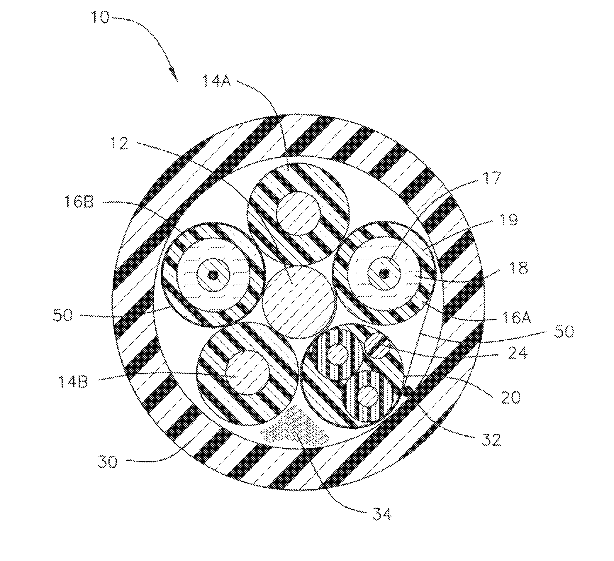
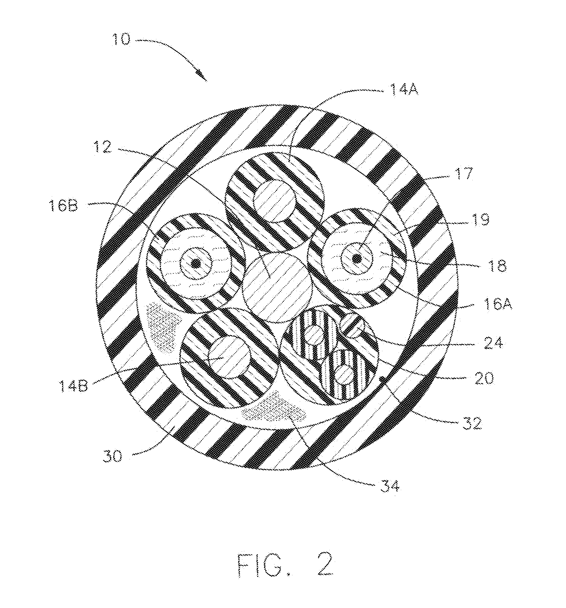
[0016]In one embodiment, as shown in FIG. 2, a composite cable 10 is shown having a central grounding member 12. Preferably, central grounding member 12 is constructed as a copper wire, such as size 14 (AWG) copper wire, however, the invention is not limited in that respect.

[0017]Surrounding central grounding member 12, are two conductor wires 14A and 14B. Preferably, conductor wires 14 are constructed as copper wires, such as size 18 (AWG) copper wire, however, the invention is not limited in that respect. Conductor wires 14 make up the electrical carrier component of composite cable 10.

[0018]In one arrangement, in the case of grounding member 12 and conductors 14, fine stranded tinned copper is used to improve the flexibility of those members and thus the entire cable 10 as a whole.

[0019]Also positioned around central grounding member 12, are two fiber optic elements 16A and 16B. Preferably, fiber optic elements 16 are tight buffer optical fibers 17, surrounded by an aramid filler...


PUM


Abstract

A composite cable includes at least two optical fiber components and at least one additional component. An irradiated crosslinked jacket surrounds the optical fiber component and the at least one additional component. A shield encloses at least the two optical fiber components within the jacket, where the shield protects the optical fibers from irradiation of the crosslinked jacket.

Description

BACKGROUND[0001]1. Field of the Invention[0002]This application relates to cables. More particularly, this application relates to composite fiber optic, power and signal type cables.[0003]2. Related Art[0004]In the art of cable production, composite cables are cables that combine both power conductors as well as signal cables within a single outer jacket. Such cables can be used for many self contained power / signal transmission connections. A common use for such composite cables is for connecting cameras, such as CCD security cameras, for providing power, signal transmission and actuator control of the camera. See for example prior art FIG. 1 wherein various cable types are included within a single jacket.[0005]A number of such composite cables are offered with various constructions, typically as an assembly of copper and fiber elements. However, such prior art cables lack the ability to deliver the power necessary over distances of 300 to 5000 ft, nor the ability to carry a 20-400 ...

Claims


Application Information

Patent Timeline
Patent Type & Authority Patents(United States)
IPC IPC(8): G02B6/44
CPCG02B6/4416G02B6/443G02B6/4432
Inventor KELLER, DAVIDKROUSHL, PAULCHU, WAYNE
Owner NEXANS
Why Eureka
Try Eureka