Conversion valve

A switching valve and rotary cap technology, applied in the field of switching valves, can solve problems such as high cost, hidden dangers of oil circuit sealing, complex structure of oil circuit switching valves, etc., and achieve the effect of reducing costs and being convenient to use

Active Publication Date: 2017-01-11
HANGZHOU OUDUN ELECTROMECHANICAL
View PDF4 Cites 12 Cited by
  • Summary
  • Abstract
  • Description
  • Claims
  • Application Information

AI Technical Summary

Problems solved by technology

However, in the hydraulic cylinder of this structure, the structure of the oil circuit switching valve is complicated and the distribution of the oil circuit is also very complicated.

Method used


Image

  • Conversion valve
  • Conversion valve
  • Conversion valve

Examples


Embodiment Construction

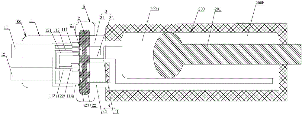
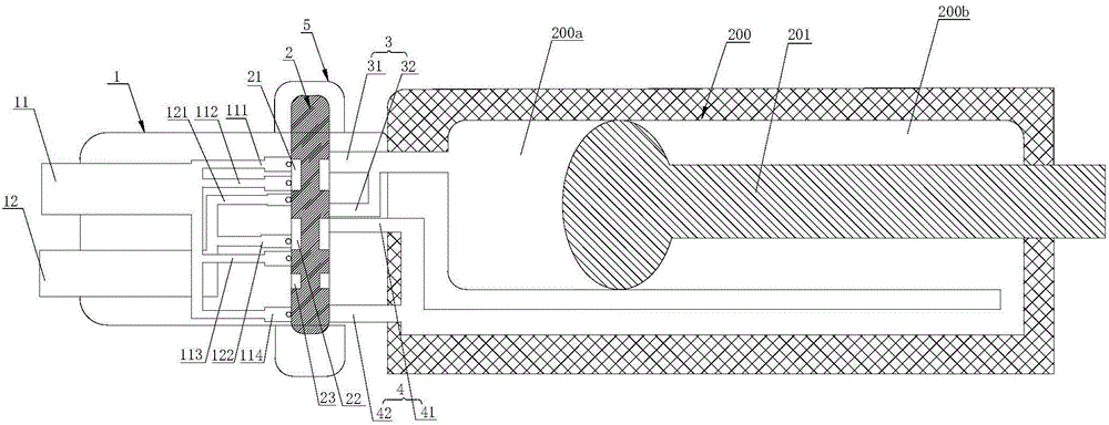
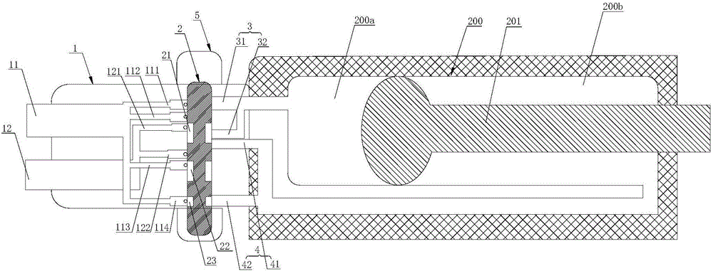
[0028] The switching valve provided in this embodiment includes a housing 1 , a switching control 2 , a first connecting pipe 3 and a second connecting pipe 4 . The housing 1 has a fluid inlet 11 and a fluid outlet 12 inside. The conversion control 2 is arranged in the housing 1 along the axial direction perpendicular to the housing 1. The conversion control 2 has a plurality of through holes whose axes are parallel to the direction of the fluid inlet 11. When the flow direction is converted, the conversion control 2 is vertical to the housing 1. axial movement. The first connecting pipe 3 and the second connecting pipe 4 are respectively connected to the conversion control 2 and the external sealing device to form a fluid circulation.

[0029] Specifically, the conversion control 2 is provided with three through holes at equal intervals, the fluid inlet 11 includes four inflow branch pipes with equal diameters, the fluid outlet 12 includes three outflow branch pipes with a d...


PUM


Abstract

The invention provides a conversion valve which comprises a shell, a conversion control part, a first connection pipe and a second connection pipe, wherein a fluid inlet and a fluid outlet are formed in the shell; the conversion control part is arranged in the shell in the axial direction perpendicular to the shell; a plurality of through holes with the axial lines parallel to the direction of the fluid inlet are formed in the conversion control part; during conversion of the flowing direction, the conversion control part moves in the axial direction perpendicular to the shell; the first connection pipe and the second connection pipe are respectively connected to the conversion control part and an external closing device to form fluid circulation.

Description

technical field [0001] The invention relates to the field of hydraulic machinery, and in particular to a switching valve. Background technique [0002] A diverter valve is a component that changes the direction of fluid. In order to realize the reciprocating movement of the piston in the hydraulic cylinder, it is usually necessary to set a switching valve in the hydraulic cylinder that can change the direction of the oil circuit. There are usually two structures of existing hydraulic cylinders. One is: the oil circuit in the hydraulic cylinder can only circulate in one direction after entering the hydraulic cylinder body, that is, it can only drive the piston to move forward, and the retreat of the piston requires manual oil drainage. It can be realized only after the operation, and it is very inconvenient for users to use, and the operation efficiency is very low. [0003] Another method is: in order to realize the automatic retraction of the piston, the hydraulic cylinde...

Claims


Application Information

Patent Timeline
Patent Type & Authority Applications(China)
IPC IPC(8): F15B13/02
CPCF15B13/02
Inventor 王俊
Owner HANGZHOU OUDUN ELECTROMECHANICAL
Why Eureka
Try Eureka