Pressure retractable cleaning device

A cleaning device and telescopic technology, which is applied in the field of pressure-retractable cleaning devices, can solve the problems of high price of cylinders, inability to meet the requirements of simple structure and convenient use of cleaning devices, and inability to complete cleaning at one time, achieving low production cost and satisfying The market needs, the effect of easy installation and disassembly

Active Publication Date: 2017-02-22
翰林航宇(天津)实业有限公司
View PDF9 Cites 12 Cited by
  • Summary
  • Abstract
  • Description
  • Claims
  • Application Information

AI Technical Summary

Problems solved by technology

However, since the upper surface of the cleaning ball is generally not cleaned, it needs to be thoroughly cleaned to prevent powder accumulation, and the cleaning ball needs to be disassembled for thorough cleaning. This kind of non-retractable cleaning ball needs to be installed manually before each cleaning procedure, and cleaning cannot be completed at one time.
In addition, the cleaning ball is installed on the cylinder, and the cleaning ball is pushed into the inside of the equipment by using the reverse action of the cylinder for cleaning; when the cleaning equipment is not in use, the cylinder pulls the cleaning ball back, and the cleaning ball inside the equipment The protruding position is blocked, and there is no powder accumulation on the surface. However, this kind of telescopic cleaning device driven by the cylinder, because the price of the cylinder is relatively high, must have compressed air as the medium when using it, which can no longer meet the needs of the market for cleaning devices. The requirements of simple structure and easy to use are gradually eliminated

Method used


Image

  • Pressure retractable cleaning device
  • Pressure retractable cleaning device
  • Pressure retractable cleaning device

Examples


Embodiment 1

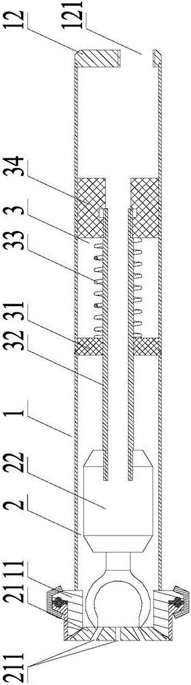
[0028] Such as figure 1 As shown, a pressure telescopic cleaning device provided in Embodiment 1 of the present invention includes a lumen assembly 1 , a cleaning assembly 2 and a telescopic assembly 3 , and the cleaning assembly 2 and the telescopic assembly 3 are connected and sheathed in the lumen assembly 1 .

[0029] The lumen assembly 1 is a cylindrical structure, with an inner clamp joint 11 at one end and an end blocking plate 12 at the other end. The end blocking plate 12 is provided with an opening 121 along the axial direction of the lumen assembly 1 .

[0030] The cleaning assembly 2 includes a cleaning ball blocking plate 21 and a cleaning ball 22. The cleaning ball blocking plate 21 is provided with a cleaning medium outlet 211, and the end is closely matched with the outer end surface of the inner clamp joint 11. The cleaning ball 22 is a cavity structure. The ends are respectively fixedly connected with the cleaning ball blocking plate 21 and the telescopic ass...

Embodiment 2

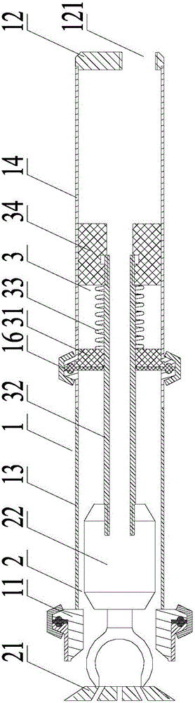
[0035] The pressure telescopic cleaning device provided in Embodiment 2 of the present invention is similar in structure to the pressure telescopic cleaning device provided in Embodiment 1 of the present invention, the difference is that the lumen assembly 1 consists of a first lumen 13 and The second lumen 14 is spliced ​​by the clamp 15, and the first fixed sleeve 31 is fixedly clamped between the first lumen 13 and the second lumen 14. In addition, the first lumen 13 and the first fixed sleeve There is also a first sealing ring 16 between 31, and the first sealing ring 16 is a silicone sealing ring.

[0036] The working principle and working process of the pressure telescopic cleaning device provided in this embodiment are similar to those in Embodiment 1, and will not be described in detail here. The structural diagram in its working state is as follows figure 2 shown.

Embodiment 3

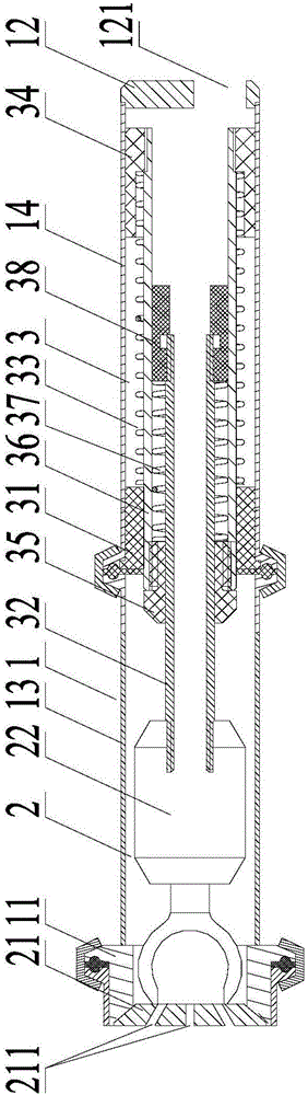
[0038] Such as image 3As shown, the pressure telescopic cleaning device provided in Embodiment 3 of the present invention is similar in structure to the pressure telescopic cleaning device provided in Embodiment 2 of the present invention, the difference is that the telescopic assembly 3 also includes a second fixed Sleeve 35, second connecting pipe 36, second spring 37 and second movable sleeve 38, second fixed sleeve 35, second connecting pipe 36, second spring 37 and second movable sleeve 38 are socketed together Forming an integral telescopic clamp between the first connecting pipe 32 and the first spring 33, the second connecting pipe 36 is telescopically sleeved in the first spring 33, and one end is fixedly arranged in the inner hole of the first movable sleeve 34, The other end passes through the first fixed sleeve 31 and is movably sleeved in the lumen assembly 1, and the second fixed sleeve 35 is fixedly arranged in the inner hole of the second connecting pipe 36 ne...


PUM


Abstract

The invention provides a pressure retractable cleaning device, which comprises a pipe cavity assembly, and a cleaning assembly and a retractable assembly arranged in the pipe cavity assembly in a sleeving way. The cleaning assembly is of a cavity structure; one end of the cleaning assembly is tightly matched with the pipe cavity assembly; cleaning medium outlets are formed in the end part; the other end of the cleaning assembly is fixedly connected with the retractable assembly in a sleeving way; and the retractable assembly is a retractable moving part with a pore passage inside. According to the pressure telescopic cleaning device provided by the invention, a cleaning ball block board fits to an inner wall of a cavity body to be cleaned, so that the defect that the cleaning device is manually installed before a cleaning program every time is avoided; in addition, during cleaning, high-pressure water or compressed gas can be adopted as power and is automatically retracted into the cleaning device after finishing cleaning, so that the defect that an existing retractable cleaning device requires an external air cylinder as a drive device is avoided; and the pressure retractable cleaning device provided by the invention is reasonable in structural design, low in production cost, convenient to assemble and disassemble, and good in cleaning effect, has no need for self-cleaning, can meet the market demand, and has a wider application prospect.

Description

technical field [0001] The invention relates to the field of cleaning tools, in particular to a pressure telescopic cleaning device. Background technique [0002] In the field of food and drug production, some storage tanks, reaction tanks and other containers generally need to be equipped with in-place cleaning devices, such as the wet method and drying machines used in pharmaceutical factories, which require thorough cleaning and need to be equipped with cleaning devices that can clean the containers. Carry out effective cleaning and meet the requirements of higher hygiene level. [0003] Most of the existing cleaning devices are non-retractable cleaning balls, which are fixedly installed on the equipment. When cleaning is needed, the cleaning balls are used to spray water to clean the equipment. However, since the upper surface of the cleaning ball is generally not cleaned, it needs to be thoroughly cleaned to prevent powder accumulation, and the cleaning ball needs to b...

Claims


Application Information

Patent Timeline
Patent Type & Authority Applications(China)
IPC IPC(8): B08B9/093B08B13/00
CPCB08B9/093B08B13/00
Inventor 侯正勋张士威雷庆玲王建
Owner 翰林航宇(天津)实业有限公司
Why Eureka
Try Eureka