A pressure-stabilizing pilot relief valve

A technology of pilot-operated relief valve and pilot-operated valve, which is applied in the direction of fluid pressure actuators, servo motor components, mechanical equipment, etc., can solve the problems of large pressure adjustment deviation, influence on pressure stability, and low flow rate, etc., to achieve Reduce the probability of howling and increase the effect of stability

Active Publication Date: 2018-07-20
HUAQIAO UNIVERSITY
View PDF6 Cites 2 Cited by
  • Summary
  • Abstract
  • Description
  • Claims
  • Application Information

AI Technical Summary

Problems solved by technology

[0003] The commonly used direct-acting relief valve, due to the limitation of spring stiffness and flow rate, the flow rate is generally not very large, and the pressure regulation deviation is large, and the ability to resist flow fluctuations is poor.
[0004] Due to the pressure regulation function of the pilot stage, the pilot-operated relief valve has a smaller pressure regulation deviation than the direct-acting relief valve, but there are still inevitable pressure regulation deviations and the disadvantages of changes with the fluctuation of inlet pressure and flow. Affects the pressure stability when the system works
[0005] Moreover, due to processing errors and structural design problems, the general overflow valve is prone to whistling, which causes the pressure of the hydraulic system to fluctuate, which in turn causes the vibration of the system pipeline and the flow pulsation of other hydraulic components, resulting in vibration and noise, which affects the hydraulic system. Work stability, and reduce the comfort of the environment around the hydraulic system

Method used


Image

  • A pressure-stabilizing pilot relief valve

Examples


Embodiment Construction

[0023] The present invention will be further described in detail below in conjunction with the accompanying drawings and embodiments.

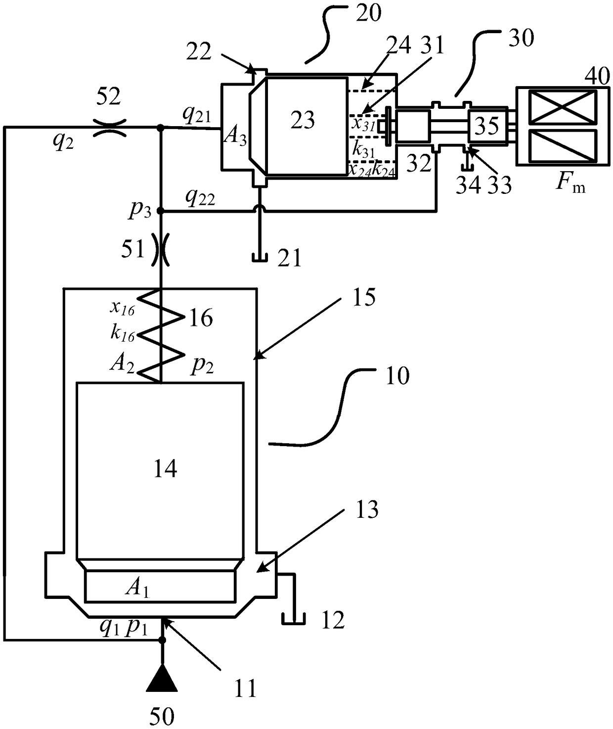
[0024] In order to solve the problems of unstable pressure and whistling in the prior art pilot-operated relief valve, the present invention provides a stable-pressure pilot-operated relief valve, such as figure 1 As shown, including main valve 10, pilot valve 30, comparator 20, system hydraulic pressure source 50 respectively acts on the spool of main valve 10, pilot valve 30, comparator 20, comparator 20 is connected with pilot valve 30, comparator 20 Dynamic adjustments are made according to changes in the inlet pressure or flow of the relief valve, so that the inlet pressure acting on the main valve 10 is considered stable within the allowable error. Wherein, a feedback spring is provided between the comparator 20 and the pilot valve 30 to keep the pressure at the upper and lower sides of the main valve core 14 of the main valve 10 constan...


PUM


Abstract

The invention relates to a stable-pressure pilot overflow valve. The stable-pressure pilot overflow valve comprises a main valve, a pilot valve and a comparator; a system hydraulic source is respectively acted on valve elements of the main valve, the pilot valve and the comparator; and the comparator is connected with the pilot valve, and performs dynamic adjustment according to the pressure or flow change in an inlet of the overflow valve to enable the pressure acted in an inlet of the main valve to be stable and invariable in an allowed error. When the pressure and the flow in the inlet of the overflow valve are changed, through feedback of the comparator, the flow or pressure change is converted to the displacement of the valve element of the comparator, and is converted to the displacement of the valve element of the pilot valve through a pilot valve spring, so that the control valve port openness of the pilot valve is changed, and the pressure of an upper cavity of the valve element of the main valve is adjusted to cause change of a valve port of the main valve so as to enable the main valve to adapt to the inlet pressure or flow fluctuation. The valve element of the comparator adopts a slide cone valve structure; the valve element of the pilot valve adopts a slide valve structure; and the comparator spring and the pilot valve spring improve the system stability to reduce the squealing probability of the overflow valve.

Description

technical field [0001] The invention relates to the field of relief valves, in particular to a pressure-stabilizing pilot relief valve. Background technique [0002] The relief valve is an important part of the hydraulic system, which plays a pivotal role in preventing system overload and maintaining system pressure stability. [0003] The commonly used direct-acting relief valve, due to the limitation of the spring stiffness and the flow rate, the flow rate is generally not very large, and the pressure regulation deviation is large, and the ability to resist flow fluctuations is poor. [0004] Due to the pressure regulation function of the pilot stage, the pilot-operated relief valve has a smaller pressure regulation deviation than the direct-acting relief valve, but there are still inevitable pressure regulation deviations and the disadvantages of changes with the fluctuation of inlet pressure and flow. Affects the pressure stability when the system is working. [0005] ...

Claims


Application Information

Patent Timeline
Patent Type & Authority Patents(China)
IPC IPC(8): F15B13/02
CPCF15B13/021
Inventor 任好玲林添良陈强缪骋陈其怀付胜杰
Owner HUAQIAO UNIVERSITY
Why Eureka
Try Eureka