
A temperature self-regulating device in a tunnel kiln
A self-regulating and internal temperature technology, which is applied in the direction of furnace, furnace type, lighting and heating equipment, etc., can solve the problems of large temperature difference between upper and lower, difficult turbulent flow of gas and air, and insufficient combustion, so as to increase the mixed combustion area of gas and solve the problem of The problem of the temperature difference between the upper and lower sides and the effect of reducing the amount of production
- Summary
- Abstract
- Description
- Claims
- Application Information
AI Technical Summary
Problems solved by technology
Method used
Image

Examples
Embodiment 1
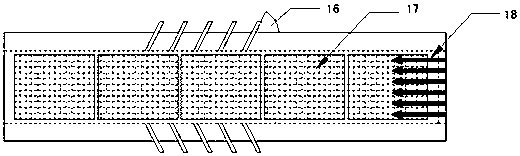
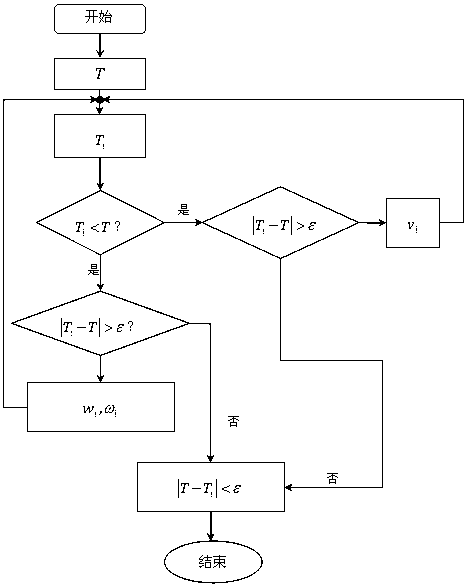
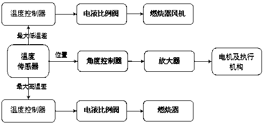
[0028] Such as Figure 1~Figure 2 As shown, a self-regulating device for temperature in the kiln includes: a kiln body, a temperature adjustment burner 3 arranged on the side wall of the kiln body, a blower 18 arranged at the end of the kiln body, a temperature sensor arranged in the kiln body, and PID control It also includes a first motor 9, a second motor 19, a first connecting shaft 10, a second connecting shaft 20, a first connecting block 11, a spherical surface pair 12, and a second connecting block arranged outside the kiln body 13 and the rotating hinge base 15, wherein the first connecting shaft 10 and the second connecting shaft 20 are perpendicular to each other, the first motor 9 is drivingly connected to one end of the first connecting shaft 10 through a gear transmission pair, and the second motor 19 is driven by a gear The pair is in transmission connection with one end of the second connecting shaft 20, and the other end of the first connecting shaft 10 and the...
PUM
 Abstract
Description
Claims
Application Information