
Temperature self-adjusting device for inner tunnel kilns

A self-regulating and internal temperature technology, which is applied in the direction of furnace types, furnaces, lighting and heating equipment, etc., can solve the problems of large temperature difference between upper and lower, difficult turbulent flow of gas and air, and insufficient combustion, so as to increase the gas mixed combustion area and solve the problem of The problem of the temperature difference between the upper and lower sides and the effect of reducing the amount of production

Active Publication Date: 2017-02-22
YANCHENG INST OF TECH
View PDF4 Cites 3 Cited by
  • Summary
  • Abstract
  • Description
  • Claims
  • Application Information

AI Technical Summary

Problems solved by technology

[0003] 1. The original tunnel kiln changes the temperature in the kiln by changing the speed of air and gas. The sintering temperature has a large range of changes, and the range of gas flow rate changes cannot be accurately controlled, which affects the sintering quality of refractory materials.
[0004] 2. In the combustion process of the original tunnel kiln, gas and air are not easy to turbulence, that is, it is not easy to fully mix, the combustion is not sufficient, and a large amount of polluting gas is generated during the process, and the amount of polluting gas generated is not easy to control
[0005] 3. The original tunnel kiln has a low degree of intelligence, and cannot adjust the speed ratio of air and gas according to the temperature change in the kiln in real time, and the adjustment of the burner angle, etc.
[0006] Fourth, the original tunnel kiln has a large temperature difference between the upper and lower sides of the kiln when sintering refractory materials, and the effect of taking various measures to reduce the temperature difference in the kiln is not obvious

Method used


Image

  • Temperature self-adjusting device for inner tunnel kilns
  • Temperature self-adjusting device for inner tunnel kilns
  • Temperature self-adjusting device for inner tunnel kilns

Examples


Embodiment 1

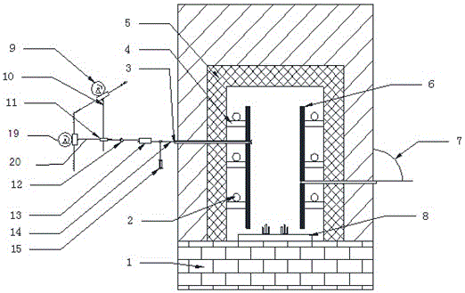
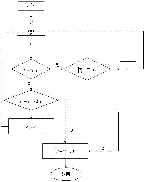
[0028] Such as Figure 1~Figure 2 As shown, a temperature self-regulating device in a kiln includes: a kiln body, a temperature-regulating burner 3 arranged on the side wall of the kiln body, a blower 18 arranged at the tail of the kiln body, a temperature sensor arranged in the kiln body, and a PID control device, and controller; also includes a first motor 9, a second motor 19, a first connecting shaft 10, a second connecting shaft 20, a first connecting block 11, a spherical pair 12, and a second connecting block arranged outside the kiln body 13 and a rotating hinge seat 15, wherein the first connecting shaft 10 and the second connecting shaft 20 are perpendicular to each other, the first motor 9 is connected to one end of the first connecting shaft 10 through a gear transmission pair, and the second motor 19 is driven through a gear One end of the pair and the second connecting shaft 20 is connected by transmission, and the other end of the first connecting shaft 10 and t...


PUM


Abstract

The invention discloses a temperature self-adjusting device for inner tunnel kilns. The device comprises a kiln body, a temperature adjustment burner which is installed on the side wall of the kiln body, a blower which is installed at the end part of the kiln body, a temperature sensor which is installed inside the kiln body, a PID controller and a central controller, and a temperature adjustment burner angle adjusting mechanism. The device of the invention can control the angle of the temperature adjustment burner nozzle, the fuel gas injection speed, the speed of temperature adjustment burner nozzle, and the kiln tail blowing rate of the tunnel kiln; sintering researches on various refractory materials can be carried out, which increases the diversity of researches; compared with the original tunnel kilns, the accuracy of temperature adjustment is increased, the efficiency is increased, the reaction rate of execution mechanism is faster, the automatic degree is higher with less pollution, and environmental protection and energy saving performance are improved.

Description

technical field [0001] The invention relates to a temperature self-regulating device in a tunnel kiln. Background technique [0002] The burners of the original tunnel kiln are directly installed on both sides of the tunnel kiln or on the kiln roof. The position of the burner is fixed, that is, the angle of the burner cannot be adjusted. The kiln walls on both sides and the kiln roof are piled with refractory materials. In the original tunnel kiln, the temperature in the kiln can only be changed by changing the injection speed of air and gas and extensively adjusting the blast speed in the kiln. Its fatal disadvantages are: [0003] 1. The original tunnel kiln changes the temperature in the kiln by changing the air and gas velocity. The sintering temperature has a large variation range, and the gas flow rate variation range cannot be accurately controlled, which affects the sintering quality of refractory materials. [0004] 2. In the original tunnel kiln, the gas and air ...

Claims


Application Information

Patent Timeline
Patent Type & Authority Applications(China)
IPC IPC(8): F27B9/40F27B9/36F27B9/30F27B9/04
CPCF27B9/045F27B9/30F27B9/36F27B9/40
Inventor 许宁王雪峰许玥李亮
Owner YANCHENG INST OF TECH
Learn More