Device and method for removing CO2 from flue gas in power plant by using fly ash

The technology of fly ash and charging device is applied in the direction of separation method, chemical instrument and method, gas treatment, etc. It can solve the problems of low utilization efficiency of fly ash and high energy consumption of decarbonization process, and achieve simple structure, equipment and Low operating cost and low running resistance

Active Publication Date: 2017-03-08
NANJING NORMAL UNIVERSITY
View PDF4 Cites 3 Cited by
  • Summary
  • Abstract
  • Description
  • Claims
  • Application Information

AI Technical Summary

Problems solved by technology

However, the utilization efficiency of fly ash is low, and the energy consumption of the decarbonization process is high, so the system needs to be further optimized

Method used


Image

  • Device and method for removing CO2 from flue gas in power plant by using fly ash

Examples


Embodiment approach

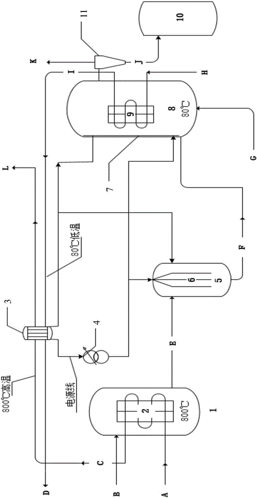
[0025] Such as figure 1 As shown, an embodiment of the present invention, the device includes an activation reactor 1, a heating buried pipe 2, a thermoelectric generator 3, a transformer 4, a charging device 5, an electrode wire 6, an electrode plate 7, a fluidized bed 8, a heat dissipation Buried pipe 9, cyclone separator 11, waste bin 10. The output end of the activation reactor 1 is connected to the charging device 5; the output end of the charging device 5 is connected to the fluidized bed reactor 8; the output end of the fluidized bed reactor 8 is connected to the cyclone separator 11; the cyclone separation The output end of the lower part of the device 11 is connected to the upper part of the waste bin 10; the heating buried pipe 2 is buried in the activation reactor 1 and connected to the front end flue A of the boiler superheater, which is used for circulating high-temperature flue gas to provide activation energy; Buried cooling coils 9 are connected to the branch ...


PUM


Abstract

The invention discloses a device for removing CO2 from flue gas in a power plant by using fly ash. The device comprises an activation reactor, a charging device, a fluidized bed, a cyclone separator and a waste material bin, wherein the output end of the activation reactor is connected with the charging device; the output end of the charging device is connected with the fluidized bed; the output end of the fluidized bed is connected with the cyclone separator; and the output end of the cyclone separator is connected with the waste material bin. The invention also discloses a method for removing the CO2 from the flue gas in the power plant by using the fly ash. The method comprises the following steps: conveying the fly ash into the activation reactor and carrying out activation treatment, then carrying out conveying into the charging device and carrying out charging treatment, then carrying out conveying into the fluidized bed so as to remove the CO2 in the flue gas, and finally carrying out conveying into the waste material bin. According to the invention, the device organically combines with a coal-fired power generating system; the flue gas and cold air in the coal-fired power plant can be utilized to provide a heat source and a cold source for the device; meanwhile, needed electric energy is provided for the device through a thermoelectric power generation technology; thus, an optimization scheme capable of reducing cost and energy consumption is realized.

Description

technical field [0001] The invention relates to the field of pollutant emission reduction in the process of resource utilization of solid waste and energy utilization, more precisely, to a method for removing CO in power plant flue gas by using fly ash 2 The device and method thereof belong to the technical field of carbon dioxide capture and emission reduction. Background technique [0002] CO 2 Capture is the key to controlling CO in coal-fired power plants 2 efficient way to discharge. Capture CO from coal-fired power plant flue gas 2 There are many technical routes, which can be generally divided into: pre-combustion capture, decarbonization during combustion and post-combustion capture. post-combustion CO 2 The capture technology does not affect the upstream combustion process and is not affected by the CO in the flue gas 2 Concentration effects, no need to modify the existing power plant equipment and other advantages, can be directly used for CO in the flue gas ...

Claims


Application Information

Patent Timeline
Patent Type & Authority Applications(China)
IPC IPC(8): B01D53/83B01D53/62
CPCB01D53/62B01D53/83B01D2257/504B01D2258/0283Y02A50/20Y02C20/40
Inventor 王国栋郭亚飞赵传文王子晨谌通张华秋谢功维王菲
Owner NANJING NORMAL UNIVERSITY
Why Eureka
Try Eureka