Nose sills for shore spillway or spillway outlets

A technology of flood discharge tunnel and spillway, applied in the field of propulsion nose, can solve the problems such as the limitation of the diffusion space of the lower discharge tongue and the inability to meet the requirements of energy dissipation and anti-scour in engineering, and achieves significant energy dissipation effect, increased contact area, and pick distance. big effect

Active Publication Date: 2018-12-21
SICHUAN UNIV
View PDF3 Cites 1 Cited by
  • Summary
  • Abstract
  • Description
  • Claims
  • Application Information

AI Technical Summary

Problems solved by technology

Because the bank-type discharge structure often has a certain intersection angle with the narrow river channel, the diffusion space of the discharge tongue is limited, and the return of the water tongue to the groove and the stability of the high and steep bank slope are more prominent. Therefore, the conventional water discharge nose The sill type cannot meet the energy dissipation and anti-scour requirements of the project, so it is necessary to design a special sill structure type and layout method according to the actual characteristics of the project and local conditions, so as to ensure the reliability and safety of the project operation

Method used


Image

  • Nose sills for shore spillway or spillway outlets
  • Nose sills for shore spillway or spillway outlets
  • Nose sills for shore spillway or spillway outlets

Examples


Embodiment 1

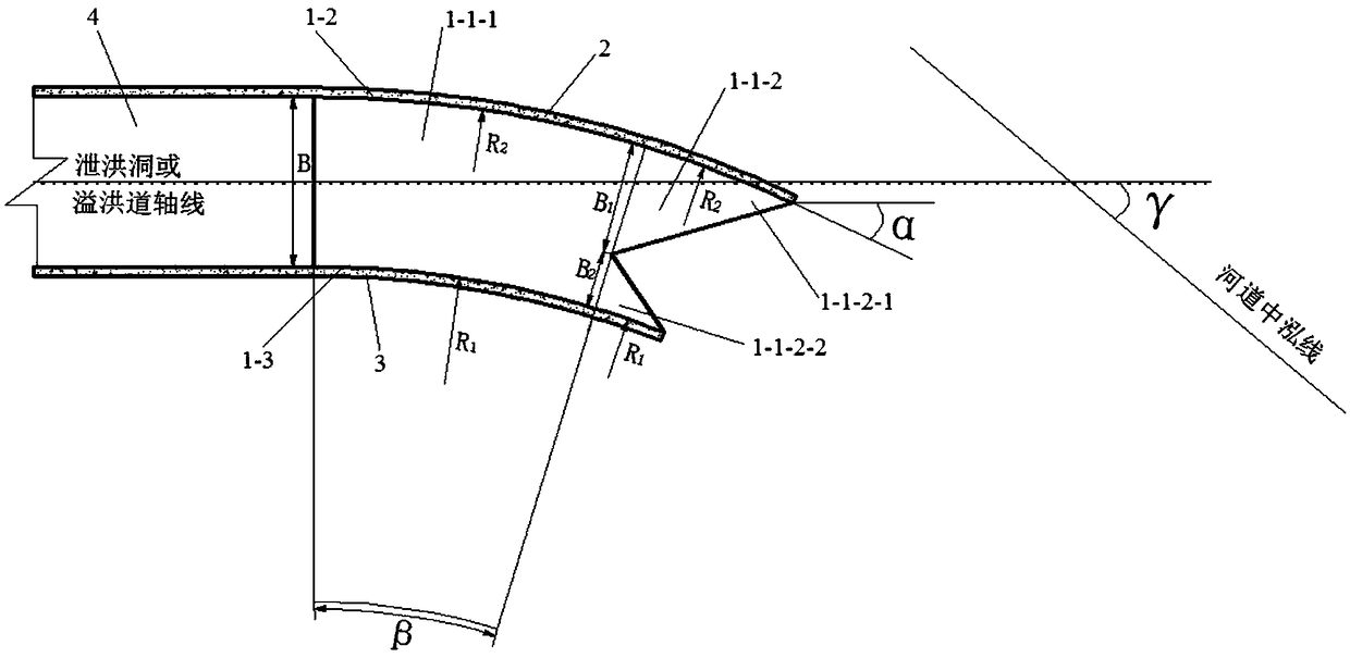
[0025] The flow-deflecting nose sill described in this embodiment is used in the flood discharge tunnel of a narrow river valley, the angle γ between the axis of the flood discharge tunnel and the center line of the river channel is 30°, and the width of the floor of the flood discharge tunnel is 9m.

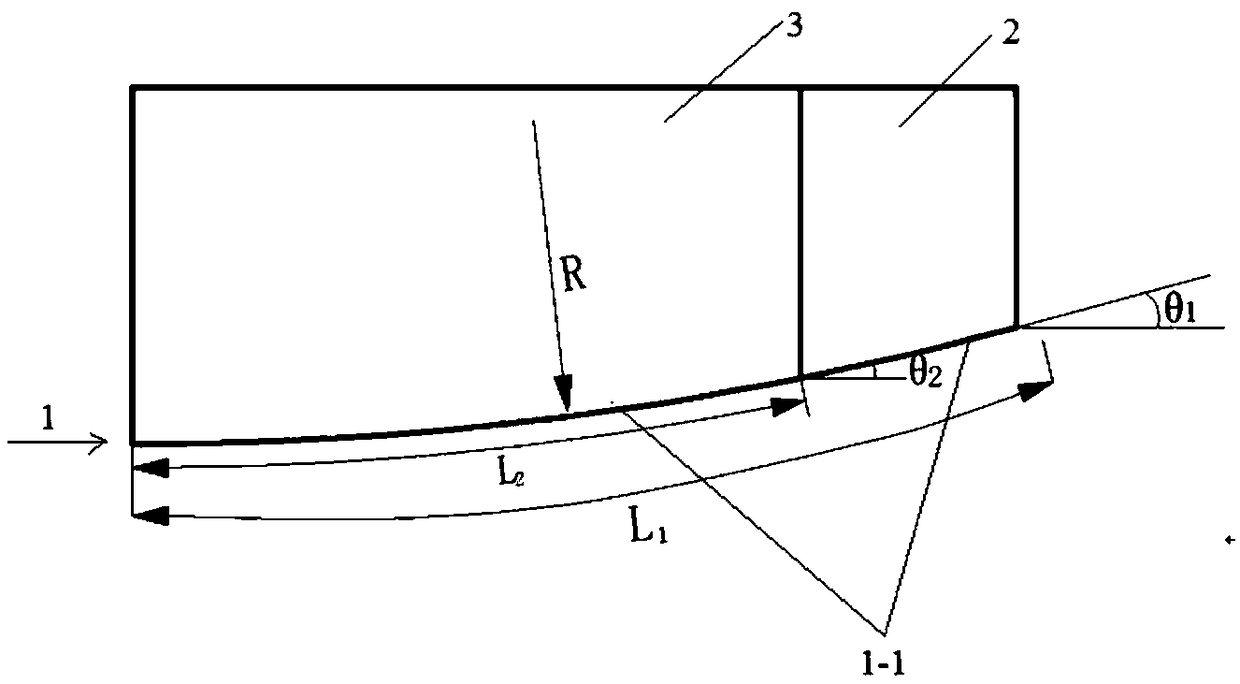
[0026] The deflecting nose sill described in the present embodiment is made of reinforced concrete, and its shape and structure are as follows: figure 1 , figure 2 As shown, it is composed of a bottom plate 1, a first side wall 2 and a second side wall 3, and the bottom plate 1 includes a water-passing surface 1-1 and two sides intersecting with the water-passing surface (the first side 1-2, the second side 1-3 ), the water passing surface 1-1 of the bottom plate is an upwardly concave arc surface, and the water passing surface 1-1 is sequentially composed of an equal arc section 1-1-1 and a toothed outlet section 1-1-2 along the water flow direction, The two sides of the equa...

Embodiment 2

[0031] The deflecting nose sill described in this embodiment is used for a bank spillway with a steep bank slope, the angle γ between the axis of the spillway and the center line of the river is 25°, and the width of the floor of the spillway is 25m.

[0032] The deflecting nose sill described in the present embodiment is made of reinforced concrete, and its shape and structure are as follows: figure 1 , figure 2 As shown, it is the same as in Example 1.

[0033] According to the specific project, the relevant dimensions of the deflected nose sill are as follows:

[0034] The bottom plate width B=25m, the total arc length L of the equal arc section of the bottom plate passing water surface and the toothed outlet section of the bottom plate passing water surface on the big tooth side 1 =30.54m, the angle θ between the tangent line of the large tooth exit of the toothed exit section of the water surface of the bottom plate and the horizontal plane 1 =π / 7.2 radian=25°, the ra...


PUM


Abstract

According to the present invention, the deflecting nose sill used for the outlet of a bank spillway or a spillway tunnel is composed of a bottom plate, a first side wall and a second side wall. The arc surface of the water passing surface is composed of an equal arc section and a tooth-shaped outlet section in sequence along the water flow direction. The tooth-shaped outlet section of the water surface is a tooth-shaped structure formed by a large tooth and a small tooth. The large tooth is located on the outside along the turning direction of the water flow. Along the inner side of the turning direction of the water flow, the radius of the outer surface is the same as the radius of the corresponding side surface of the equal arc section of the water passing surface. The invention provides a suitable deflecting nose sill for a narrow river valley bank-type spillway or the outlet of a flood discharge tunnel, and solves the scour prevention problem of the deflecting water tongue returning to the trough and the downstream river channel under the terrain condition.

Description

technical field [0001] The invention belongs to the field of flood discharge and energy dissipation facilities in water conservancy and hydropower projects, and in particular relates to a deflector nose sill used for the outlet of a bank spillway or a flood discharge tunnel. Background technique [0002] In areas with narrow river valleys and steep slopes, large-scale hydropower projects with high water head, large flow, and high-power flood discharge will be built. Whether the type of flood discharge and energy dissipation buildings is reasonable will directly affect the reliability and safety of project operation, and is an important aspect of the entire hub. Part. According to the practical experience of many projects at home and abroad, the flood discharge and energy dissipation method of high dams generally choose deflection energy dissipation. Because the bank-type discharge structure often has a certain intersection angle with the narrow river channel, the diffusion ...

Claims


Application Information

Patent Timeline
Patent Type & Authority Patents(China)
IPC IPC(8): E02B8/06
CPCE02B8/06
Inventor 王磊刁明军
Owner SICHUAN UNIV
Why Eureka
Try Eureka