Method for removing blind rivet elements from riveting equipment

A technology for blind rivets and connecting elements is applied in the field of removing blind rivet elements from riveting equipment, and can solve the problems of riveting equipment damage and time-consuming of blind rivet elements.

Active Publication Date: 2019-07-16
HONSEL DISTRIBUTION GMBH & CO KG
View PDF6 Cites 0 Cited by
  • Summary
  • Abstract
  • Description
  • Claims
  • Application Information

AI Technical Summary

Problems solved by technology

However, this leads to damage to the blind rivet elements, the workpieces to be fastened or the riveting equipment itself and is also time-consuming

Method used


Image

  • Method for removing blind rivet elements from riveting equipment
  • Method for removing blind rivet elements from riveting equipment
  • Method for removing blind rivet elements from riveting equipment

Examples


Embodiment Construction

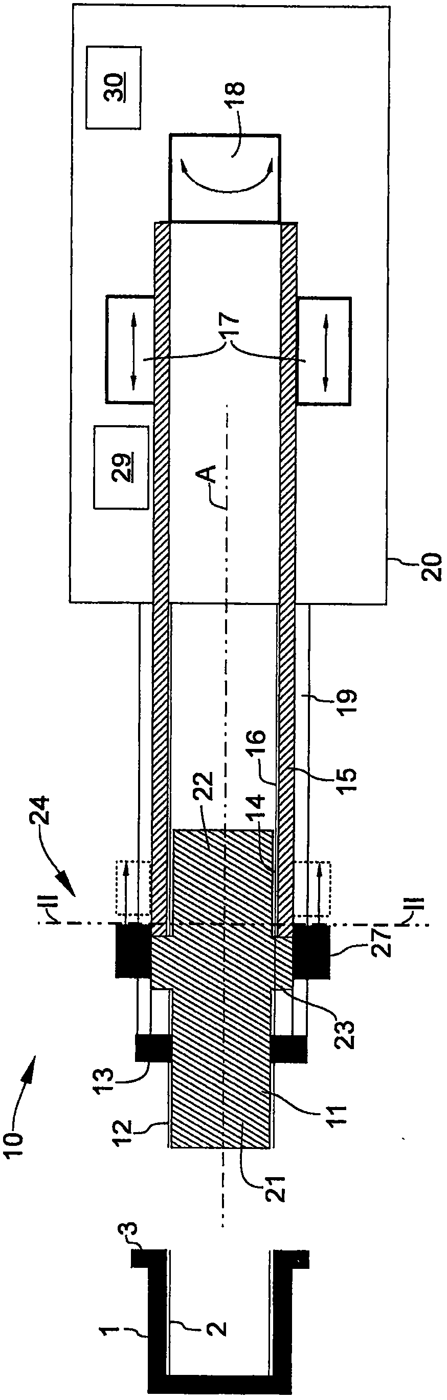
[0023] figure 1 A riveting device 10 designed to implement the method of the invention is shown. The riveting device 10 comprises a housing 20 in which a schematically indicated longitudinal drive 17 and a schematically indicated rotary drive 18 are arranged. The two drives 17 and 18 can be implemented as described in DE 10 2013 105 703 A1. In this case, the longitudinal drive 17 serves to drive the connecting element 15 along its axis of rotation A relative to the housing 20 . The rotary drive 18 serves to rotate the connecting element 15 about its axis of rotation A relative to the housing 20 .

[0024] The connecting element 15 is realized in the form of a sleeve and is mounted in the housing 20 in an axially displaceable and rotatable manner. One end of the connecting element 15 protrudes from the housing and is characterized by a second internal thread 16 in the form of a left-hand thread on its inner circumferential surface. The mandrel 11 is screwed into the second ...


PUM


Abstract

The invention relates to a method for removing a blind rivet element (1) from a riveting device (10), wherein the blind rivet element (1) is screwed to the riveting device (10) by means of a first thread arrangement (2, 12) A mandrel (11), wherein the mandrel (11) is further connected to a connecting element (15) on the riveting device (10) by means of a second thread arrangement (14, 16), and wherein the riveting device (10) includes a A longitudinal drive (19) for driving the connection element (15) axially, respectively, and a rotary drive (18) for driving the connection element (15) in rotation relative to the axis of rotation (A) of the connection element (15), respectively, wherein The method comprises the steps of: activating an emergency procedure as a result of a user input on the riveting device (10), wherein the emergency procedure causes the connecting element (15) to assume a second thread arrangement (14, 16) by means of a rotary drive (18) ) is driven in a rotational direction in which the connection between the mandrel (11) and the connecting element (15) is separated, and the rotary drive (18) stops driving the connecting element after a default value has been reached.

Description

technical field [0001] The invention relates to a method of removing blind rivet elements from a riveting device according to an embodiment of the invention. Background technique [0002] In this method, a blind rivet element is screwed to a mandrel of a riveting device by means of a first thread arrangement. The mandrel is further connected to a connection element on the riveting device by means of a second thread arrangement. The riveting device comprises a longitudinal drive for driving the connecting elements axially, respectively, and a rotary drive for driving the connecting elements rotationally, respectively, relative to a rotational axis of the connecting elements. [0003] A riveting device of this type is known, for example, from DE 10 2013 105 703 A1. [0004] However, damage to the first thread arrangement often occurs during such riveting devices and the resulting rivet assembly. When assembling blind rivet elements, such damage may necessarily occur due to ...

Claims


Application Information

Patent Timeline
Patent Type & Authority Patents(China)
IPC IPC(8): B21J15/26
CPCB21J15/26B25B27/0014B21J15/38B21J15/36
Inventor M·H·洪泽尔
Owner HONSEL DISTRIBUTION GMBH & CO KG
Why Eureka
Try Eureka