

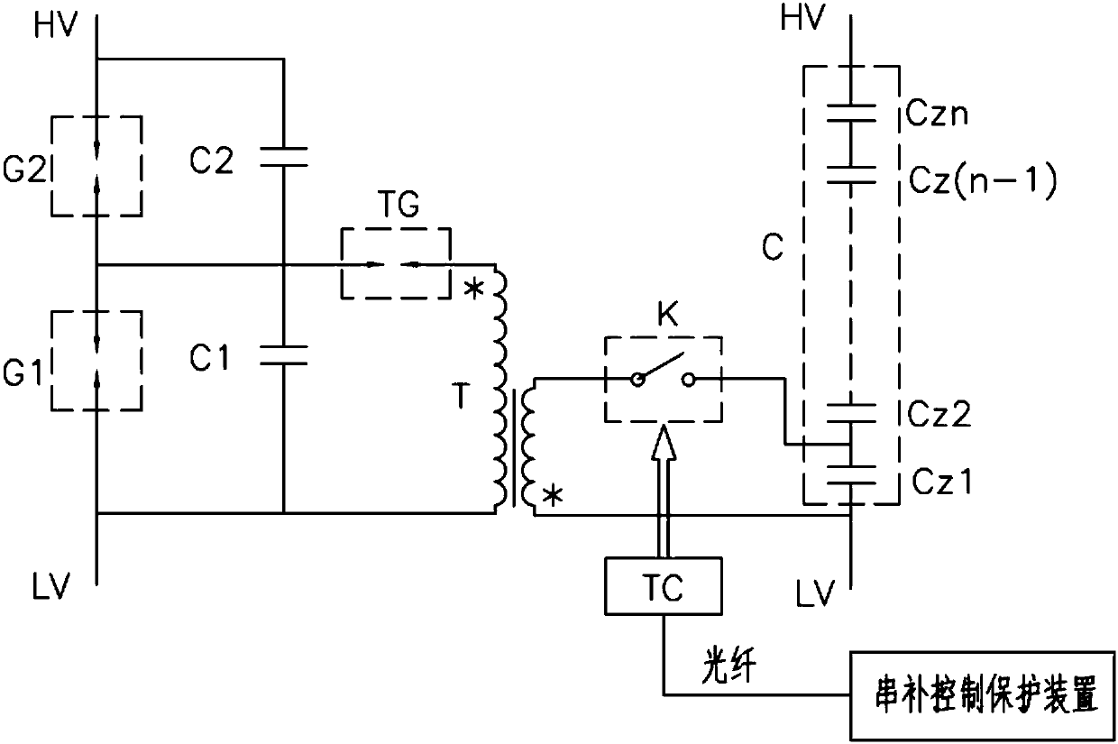
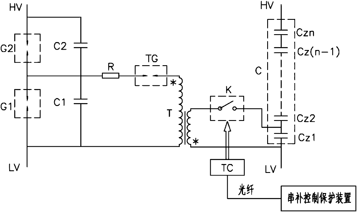
A triggered spark gap
A spark gap and air gap technology, applied to spark gaps, circuits dedicated to spark gaps, electrical components, etc., can solve the problems of complexity and many trigger system components, and achieve simple structure, simple overall structure, and improved trigger reliability. Effect
- Summary
- Abstract
- Description
- Claims
- Application Information
AI Technical Summary
Problems solved by technology
Method used
Image

Examples
Embodiment Construction
[0022] Exemplary embodiments of the present invention will now be described with reference to the drawings; however, the present invention may be embodied in many different forms and are not limited to the embodiments described herein, which are provided for the purpose of exhaustively and completely disclosing the present invention. invention and fully convey the scope of the invention to those skilled in the art. The terms used in the exemplary embodiments shown in the drawings do not limit the present invention. In the figures, the same units / elements are given the same reference numerals.
[0023] Unless otherwise specified, the terms (including scientific and technical terms) used herein have the commonly understood meanings to those skilled in the art. In addition, it can be understood that terms defined by commonly used dictionaries should be understood to have consistent meanings in the context of their related fields, and should not be understood as idealized or over...
PUM
 Abstract
Description
Claims
Application Information