key structure

A button and keycap technology, which is applied in the field of button structure with conductive structure, can solve the problems of membrane switch layer fatigue and poor trigger reliability, and achieve the effect of high trigger reliability

Active Publication Date: 2021-06-08
DARFON ELECTRONICS (SUZHOU) CO LTD +1
View PDF0 Cites 0 Cited by
  • Summary
  • Abstract
  • Description
  • Claims
  • Application Information

AI Technical Summary

Problems solved by technology

However, due to the need to overcome the resistance of the material of the membrane switch layer itself, coupled with the fatigue problem of the material of the membrane switch layer itself, the triggering reliability of the conventional button structure is not good.

Method used


Image

  • key structure
  • key structure
  • key structure

Examples


Embodiment Construction

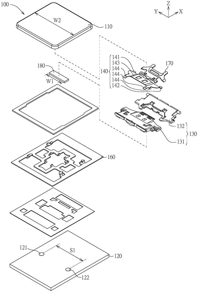
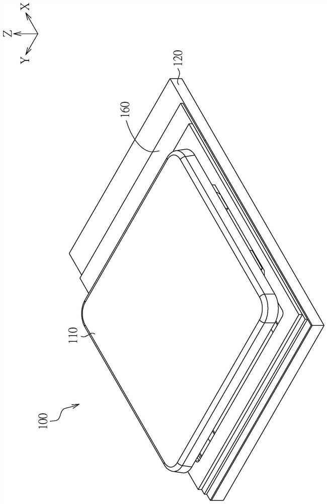
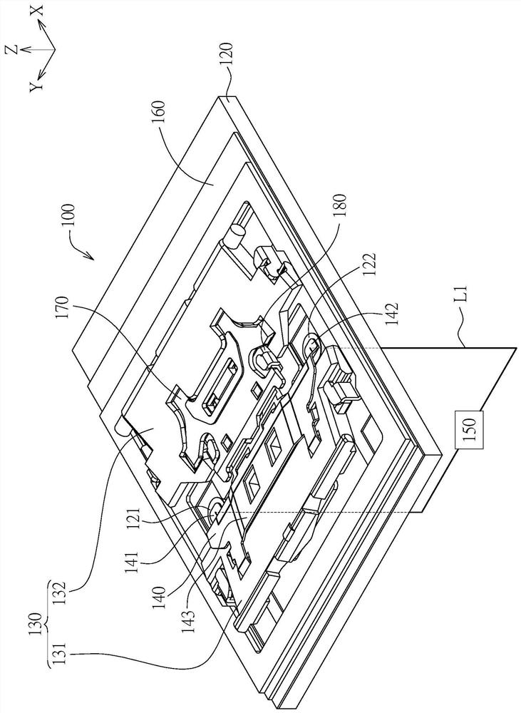
[0051] Please refer to Figure 1A to Figure 2C , Figure 1A An exploded schematic view of the key structure 100 according to the first embodiment of the present invention is shown, Figure 1B drawn in accordance with this Figure 1A A combined schematic diagram of the key structure 100 (in an unpressed state), Figure 1C draw Figure 1B The key structure 100 omits the schematic diagram of the keycap, Figure 1D draw Figure 1C A top view of the key structure 100, Figure 1E draw Figure 1D The sectional view of the key structure 100 along the direction 1E-1E', and Figure 1F draw Figure 1D The sectional view of the button structure 100 along the direction 1F-1F', Figure 2A draw Figure 1A A three-dimensional schematic diagram of the button structure 100 in a pressed state, Figure 2B draw Figure 2A a top view of the key structure 100, and Figure 2C draw Figure 2B The cross-sectional view of the button structure 100 along the direction 2C-2C'.

[0052] like F...


PUM


Abstract

The invention discloses a key structure comprising a key cap, a circuit board, a lifting mechanism and a conductive frame. The circuit board includes a first pad and a second pad. The lifting mechanism is arranged between the circuit board and the keycap, and the keycap moves up and down relative to the circuit board via the lifting mechanism. The conductive frame is arranged on the lifting mechanism to move up and down with the lifting mechanism. The conductive frame includes a first conductive part and a second conductive part respectively located above the first pad and the second pad. The moving path of the first conductive part and the moving path of the second conductive part respectively reach the first pad and the second pad. When the first conductive part and the second conductive part respectively contact the first pad and the second pad, the first pad, the first conductive part, the second conductive part and the second pad form a cross current path.

Description

technical field [0001] The invention relates to a key structure, and in particular to a key structure with a conductive structure. Background technique [0002] Most of the traditional button structures use elastic bodies to squeeze the membrane switch layer, so that the originally separated upper and lower electrodes in the membrane switch layer contact to generate a trigger signal. The membrane switch layer itself is a soft structure, so to make the upper and lower electrodes of the membrane switch layer contact, it is necessary to overcome the resistance of the material of the membrane switch layer itself, so that the upper and lower electrodes can approach and contact. However, due to the need to overcome the resistance of the material of the membrane switch layer itself, coupled with the fatigue problem of the material of the membrane switch layer itself, the triggering reliability of the conventional button structure is not good. Contents of the invention [0003] T...

Claims


Application Information

Patent Timeline
Patent Type & Authority Patents(China)
IPC IPC(8): H01H13/705H01H3/12
CPCH01H3/125H01H13/705H01H2221/04H01H2221/044
Inventor 张立德陈志宏
Owner DARFON ELECTRONICS (SUZHOU) CO LTD
Why Eureka
Try Eureka