Electronic trigger type safety tongs

A safety gear and trigger-type technology, which is applied in the field of safety protection braking devices, can solve the problems of slow overall response, increased overall space size, and increased braking capacity of safety protection braking devices, achieving small size, simple structure, Effects with high trigger reliability

Pending Publication Date: 2022-07-29
HANGZHOU HUNING ELEVATOR PARTS CO LTD
View PDF0 Cites 0 Cited by
  • Summary
  • Abstract
  • Description
  • Claims
  • Application Information

AI Technical Summary

Problems solved by technology

[0002]The traditional mechanical speed limiter has the defect that low-speed detection is difficult to achieve. Detection at low speeds can only be achieved by increasing the detection action speed, and after triggering The safety protection brake device is triggered through the mechanical linkage mechanism, and the overall response is slow
In addition, while improving the detection and control speed, the braking capacity of the safety protection braking device is also required to increase, resulting in an increase in the overall space size

Method used


Image

  • Electronic trigger type safety tongs
  • Electronic trigger type safety tongs
  • Electronic trigger type safety tongs

Examples


Embodiment 1

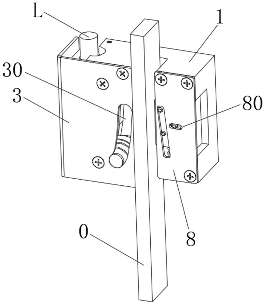
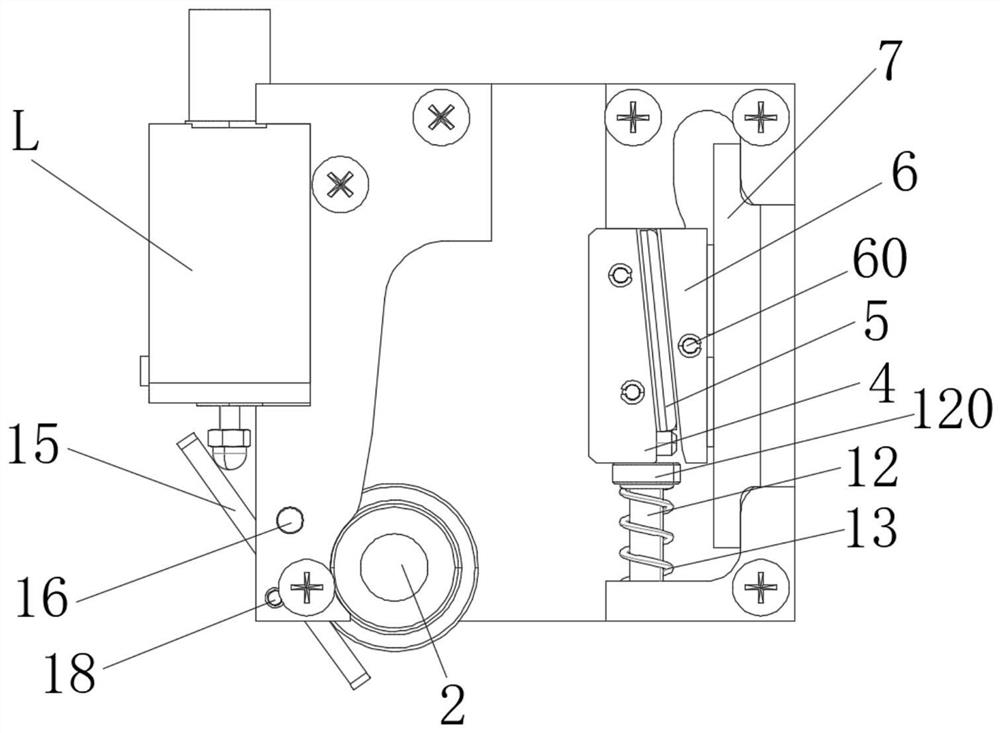
[0035] like Figure 1 to Figure 4 As shown, the electronic trigger safety gear of this embodiment includes a caliper body 1, a braking roller 2, a guide cover 3, a fixed wedge 4, a ball cage 5, a sliding seat 6, a bar-shaped leaf spring 7, a right Cover plate 8, electronic trigger L and lever mechanism.

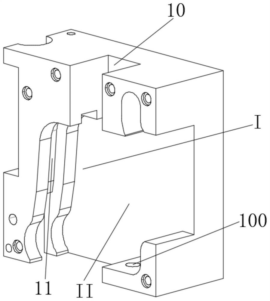
[0036] Specifically, the caliper body 1 has a vertically extending guide rail channel 10, the caliper body 1 is located on the left and right sides of the guide rail channel 10 to form a first recess I and a second recess portion II, and the first recess portion I is used for installing the brake rollers 2. The second recess II is used to install the fixed wedge 4, the ball cage 5, the sliding seat 6 and the strip spring 7, so that the brake roller 2 and the fixed wedge 4 are located on the left and right sides of the guide rail channel 10, respectively. side, so as to cooperate with the elevator guide rail 0.

[0037] Wherein, the front side of the first concave portion 1 ...

Embodiment 2

[0050] The difference between the electronic trigger safety gear of this embodiment and Embodiment 1 is:

[0051] like Figure 5 As shown, the electronic trigger L of this embodiment can also be installed on the bottom of the left side wall of the caliper body, installed obliquely, and directly use the driving end of the electromagnet to vertically drive the brake roller to move upwards to connect with the elevator guide rail. It can also realize the trigger braking of the safety gear to meet the needs of different applications;

[0052] For other structures, refer to Embodiment 1.

Embodiment 3

[0054] The difference between the electronic trigger safety gear of this embodiment and Embodiment 1 is:

[0055] like Image 6 As shown, the electronic trigger L of this embodiment can also be installed at the bottom of the left side wall of the clamp body, and the electromagnet horizontally drives the linkage frame K to drive the braking roller 2 to move upward, and contacts the elevator guide rail to achieve The horizontal drive can also realize the trigger braking of the safety gear to meet the needs of different applications;

[0056] For other structures, refer to Embodiment 1.


PUM


Abstract

The invention relates to an electronic trigger type safety gear which comprises a gear body provided with a guide rail channel, a brake roller and a fixed wedge which are installed on the gear body and located on the two sides of the guide rail channel respectively, and an electronic trigger piece installed on the gear body and used for replacing a traditional lifting mechanism. The brake roller is driven to move along the caliper body to approach the guide rail to realize braking; the two ends, in the guide rail channel direction, of the fixed wedge block abut against the clamp body and the displacement reset mechanism correspondingly, and the displacement reset mechanism is used for providing a displacement stroke for the fixed wedge block when the safety clamp is reset and resetting the fixed wedge block after displacement. According to the safety tongs, electronic triggering is achieved, and the reset force is small.

Description

technical field [0001] The invention belongs to the technical field of safety protection braking devices, in particular to an electronic trigger type safety gear. Background technique [0002] The traditional mechanical speed limiter has the defect that low-speed detection is difficult to achieve. The detection at lower speed can only be realized by increasing the detection speed, and after triggering, the safety protection braking device is triggered by the mechanical linkage mechanism, and there is an overall response. slow. In addition, when the detection and control speed is increased, the braking capacity of the safety protection braking device is also required to increase, resulting in an increase in the overall space size. In order to solve the problem of accurate detection at low speed, the matching electronic speed limiter can directly control the action of the safety protection braking device through electronic detection. [0003] The electronic speed limiter has...

Claims


Application Information

Patent Timeline
Patent Type & Authority Applications(China)
IPC IPC(8): B66B5/06B66B5/16
CPCB66B5/06B66B5/16
Inventor 邹家春姚荣康丁明星张田生朱枭
Owner HANGZHOU HUNING ELEVATOR PARTS CO LTD
Why Eureka
Try Eureka