Load-force-independent triggering device

A technology of triggering device and load force, applied in the directions of transportation and packaging, load hanging components, etc., can solve the problem of not being suitable for remote triggering of triggering devices, and achieve the effect of avoiding vertical displacement and increasing triggering reliability.

Active Publication Date: 2020-09-29
ALFRED WEGENER INST HELMHOLTZ CENT FOR POLAR & MARINE RES
View PDF6 Cites 0 Cited by
  • Summary
  • Abstract
  • Description
  • Claims
  • Application Information

AI Technical Summary

Problems solved by technology

However, neither trigger mechanism is suitable for reliable remote triggering of the trigger under the influence of disturbances from external irregularities and partly very strong force actions

Method used


Image

  • Load-force-independent triggering device
  • Load-force-independent triggering device
  • Load-force-independent triggering device

Examples


Embodiment Construction

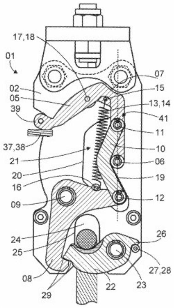
[0062] figure 1 A load-force-independent triggering device 01 for underwater applications is shown. Therefore, the materials used are resistant to sea water. The triggering device 01 is in a closed position in which a load, eg an OFOS (Ocean Ocean Observation System) in a lowered frame is held eg on a crane on a research vessel. The weight of the OFOS and the drop frame is several hundred kilograms, they act on the trigger 01 as a whole, and not on the immediate trigger area. Instead, the force is guided along it by the triggering device 01 . Thus, by applying only a low level of trigger force, it is possible to trigger the trigger device 01 independently of the applied load force.

[0063] The triggering device 01 comprises a housing 02, which in the exemplary embodiment shown consists of two structured steel plates 03, 04 (cf. image 3 ) screw together. This has the advantage that in particular movable parts can be arranged between the two steel plates 03 , 04 and thus...


PUM


Abstract

Triggering devices in which the load force of a suspended load does not act on the triggering mechanism operate in a load-force-independent manner using an advantageously low triggering force. Known triggering devices (tow couplings) operate with triggering lever, steering lever and triggering gear, which can however have undefined states with respect to one another, which can jeopardise the triggering. In the triggering device (01) according to the invention, the steering lever (10) therefore has an angular design, and in the CLOSED position of the triggering device (01) contacts a first contact surface (19) in the housing (02) and in the OPEN position of the triggering device (01) contacts a second contact surface (20) in the housing (02). The steering lever (10) only adopts defined positions in the housing (02); in the CLOSED position, said steering lever is positioned shortly before the dead-centre position (41) in relation to the triggering lever (05) and intends to open automatically. After the practically force-free unlocking of the triggering lever (05), a tension spring (14) pulls the triggering lever (05) into the defined OPEN position. The claimed triggering device (01)can thus operate reliably even under very adverse environmental conditions. In particular, it is particularly suitable, in a sea-water-resistant design, for underwater applications at great depths, for example for deploying autonomous measuring equipment.

Description

technical field [0001] The invention relates to a load force independent trigger device for a load to which a force is applied, the load being held in the closed position of the trigger device and released in the open position of the trigger device, the load force independent trigger device comprising a housing Body and trigger lever, the trigger lever is connected to the trigger pawl through the steering rod, wherein the trigger lever is rotatably mounted on the first housing shaft, the trigger pawl is rotatably mounted on the second housing shaft, and the steering rod can be Rotatably mounted on a first steering lever shaft on the trigger lever and rotatably mounted on a second steering lever axis on the trigger pawl, the load-independent triggering device also includes a force acting on the trigger lever The spring means also includes locking means by which the trigger means is secured in the closed position. [0002] Triggers are used to separate loads from equipment such...

Claims


Application Information

Patent Timeline
Patent Type & Authority Applications(China)
IPC IPC(8): B66C1/34
CPCB66C1/34B66C1/36
Inventor 约翰内斯·勒姆伯格
Owner ALFRED WEGENER INST HELMHOLTZ CENT FOR POLAR & MARINE RES
Why Eureka
Try Eureka