Resistor, in particular low-resistance current measuring resistor

A technology of current measurement and resistance value, applied in the direction of measuring electrical variables, resistance terminals/electrodes, parts of electrical measuring instruments, etc.

Inactive Publication Date: 2017-04-19
ISABELLENHUTTE HEUSLER
View PDF16 Cites 8 Cited by
  • Summary
  • Abstract
  • Description
  • Claims
  • Application Information

AI Technical Summary

Problems solved by technology

This structural design of the current measuring resistor therefore also has the disadvantages described above

Method used


Image

  • Resistor, in particular low-resistance current measuring resistor
  • Resistor, in particular low-resistance current measuring resistor
  • Resistor, in particular low-resistance current measuring resistor

Examples


Embodiment Construction

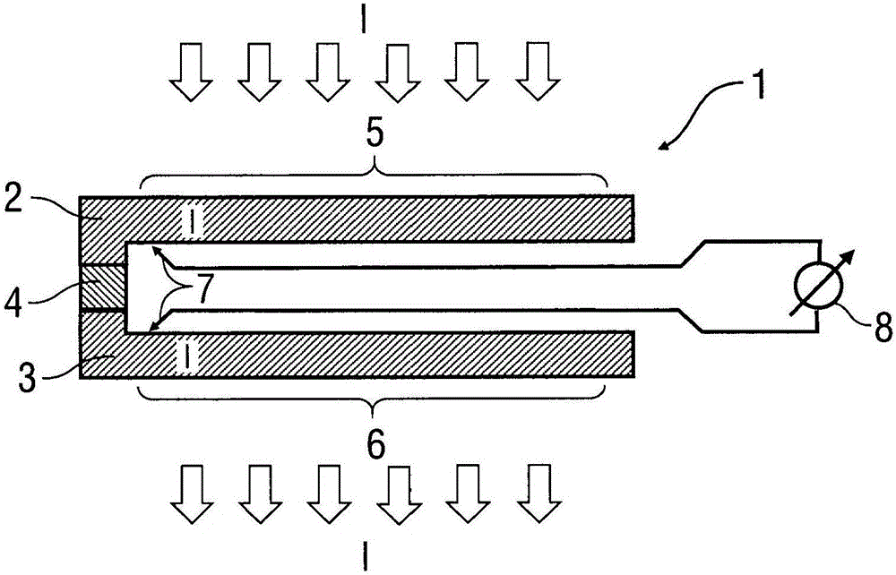
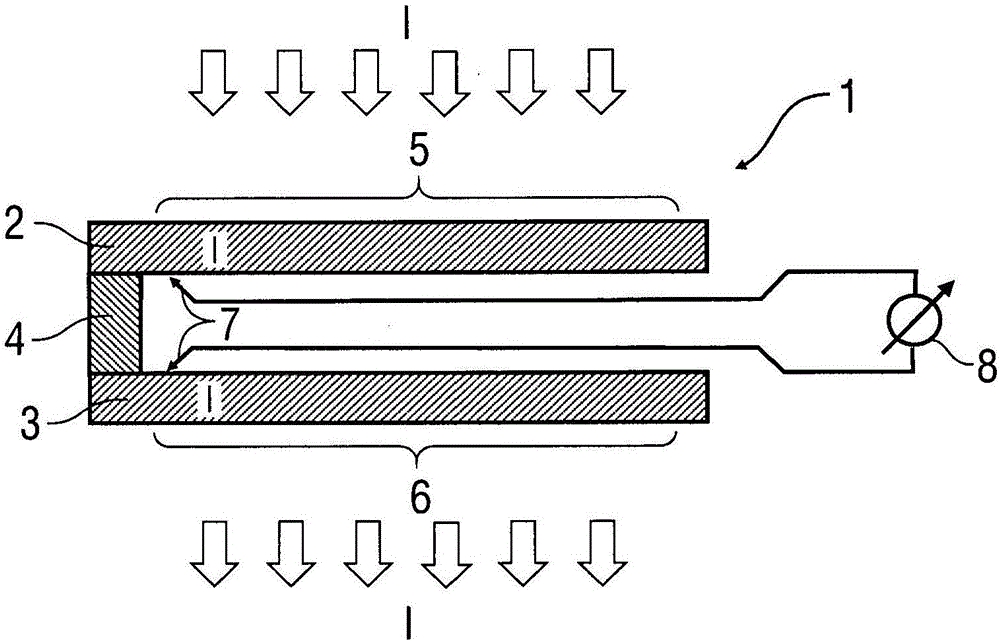
[0059] Figure 1A A cross-sectional view of a current-measuring resistor 1 according to the invention for measuring current according to the known four-conductor method is shown, said current-measuring resistor 1 being produced from a strip of composite material.

[0060] The current-measuring resistor 1 has a connection 2 for introducing a current I, which consists of an electrically conductive material such as copper or a copper alloy.

[0061] Furthermore, the current-measuring resistor 1 has a further connecting part 3 for conducting the current I out of the current-measuring resistor, said connecting part 3 consisting of the same material as the connecting part 2 or consisting of another electrically conductive material.

[0062] A resistive element 4 is arranged between the connecting portion 2 and the connecting portion 3 along the direction of current flow, the resistive element 4 is composed of a resistive material of low resistance value (such as copper-manganese-nick...


PUM


Abstract

The invention relates to a U-shaped resistor (1), in particular a low-resistance current-measuring resistor (1), comprising a first connection part (2) made of a conductive material having a first current contact surface for conducting an electrical current (I) into the resistor (1), and comprising a second connection part (3) made of a conductive material having a second current contact surface for conducting the current (I) out of the resistor (1), as well as comprising a resistor element (4) made of a resistor material, wherein the resistor element (4) is arranged in the direction of current flow between the first connection part (2) and the second connection part (3), such that the electrical current (I) flows through the electrical resistor (1). The current (I) perpendicularly enters or leaves the connections parts (2, 3) via their outer surfaces. In addition, the voltage taps are attached to the inner side of the U-shaped resistor (1), and contact the connection parts (2, 3) close to the transition to the resistor element (4).

Description

technical field [0001] The present invention relates to a resistor, especially a current measuring resistor with a relatively low resistance value. Background technique [0002] From EP 0 605 800 A1 a current-measuring resistor (“shunt”) of relatively low resistance value is known, which can be separated from a strip of composite material, which enables economical production. The known current-measuring resistor consists of two plate-shaped, flat connecting parts made of conductive material (eg copper) and a resistive material (eg copper-manganese-nickel alloy) between them. It is also composed of plate-shaped and flat resistance elements. In this arrangement, the current to be measured is led to the current measuring resistor through the connecting portion and then led out from the current measuring resistor through the other connecting portion, so that the current to be measured flows through the resistance element. In this arrangement, the actual current measurement is ...

Claims


Application Information

Patent Timeline
Patent Type & Authority Applications(China)
IPC IPC(8): G01R1/20H01C1/14
CPCG01R1/203H01C1/14H02G5/02H05K1/0306H05K1/111H05K1/181H05K2201/10022H05K2201/10151
Inventor U·黑茨勒
Owner ISABELLENHUTTE HEUSLER
Why Eureka
Try Eureka