Method for operating an electric machine

A technology of operating parameters, operating phases, applied in motor vehicles, transportation and packaging, driver input parameters, etc., can solve problems such as wear, expensive dual-mass flywheels, limiting motor vehicle power, etc.

Inactive Publication Date: 2017-04-26
AUDI AG
View PDF7 Cites 2 Cited by
  • Summary
  • Abstract
  • Description
  • Claims
  • Application Information

AI Technical Summary

Problems solved by technology

[0003] Such dual mass flywheels are relatively expensive and can wear out under high operating power
Furthermore such a dual mass flywheel can limit the power of the motor vehicle

Method used


Image

  • Method for operating an electric machine
  • Method for operating an electric machine
  • Method for operating an electric machine

Examples


Embodiment Construction

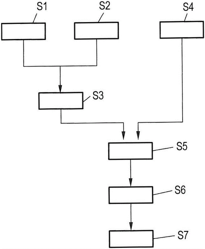
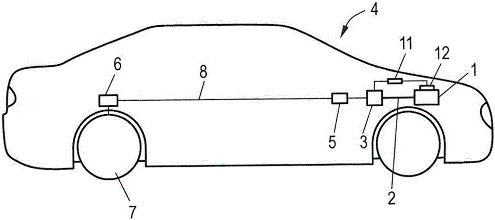
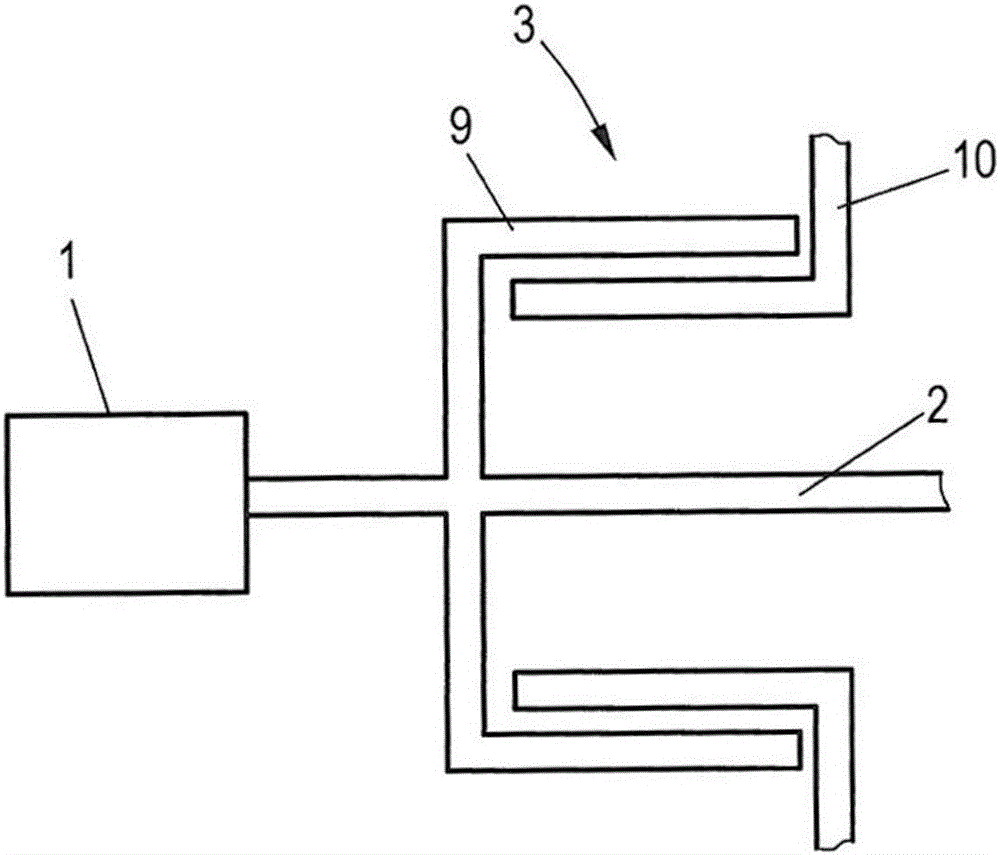
[0022] figure 1 A method for operating an electric machine coupled to an output shaft of a motor vehicle internal combustion engine is shown. The method refers to figure 2 and image 3 clarified, among which figure 2 A motor vehicle 4 is shown which comprises an internal combustion engine 1 , an output shaft 2 of the internal combustion engine 1 and an electric machine 3 coupled to the output shaft 2 . image 3 Detailed views of these components are shown.

[0023] Motor vehicle 4 is driven by internal combustion engine 1 , the torque of internal combustion engine 1 being conducted via output shaft 2 to transmission 5 , which transmits the torque to rear wheels 7 via differential 6 after transmission on layshaft 8 . The internal combustion engine 1 is a four-stroke engine, the torque of which fluctuates during the stroke of its cylinders. The cylinders of internal combustion engine 1 can supply torque to output shaft 2 only during their working strokes. During the othe...


PUM


Abstract

A method for operating an electric machine which is coupled with an output shaft of an internal combustion engine of a motor vehicle includes controlling the electric machine in dependence on at least one operating parameter of at least one of the internal combustion engine and the electric machine so that the electric machine transmits to the output shaft a compensation torque which at least partially compensates torque fluctuations of the internal combustion engine occurring during an operation of the internal combustion engine as a result of an operating phase of the internal combustion engine.

Description

technical field [0001] The invention relates to a method for operating an electric machine coupled to an output shaft of an internal combustion engine of a motor vehicle. Furthermore, the invention relates to a motor vehicle. Background technique [0002] In internal combustion engines, especially in four-stroke reciprocating piston engines, the stroke sequence of intake, compression, power generation and exhaust has the result that a temporally varying torque is transmitted from the engine to the crankshaft. It is possible that rotational vibrations are coupled into the output shaft by this time variation of the supplied torque. In order to dampen this vibration, it is known to use a so-called dual-mass flywheel, which consists of two flywheels, one of which is arranged on the engine side and the other on the transmission side, and these two flywheels are combined with elastic elements and / or Buffer connection. [0003] Such dual mass flywheels are relatively expensive a...

Claims


Application Information

Patent Timeline
Patent Type & Authority Applications(China)
IPC IPC(8): B60W20/40B60W10/08B60W30/20
CPCB60W10/08B60W20/40B60W30/20B60W2030/206B60W2540/16B60W2540/10B60W2510/08B60W2510/081B60W2510/0638B60W2710/083B60W10/06Y10S903/902B60W20/10B60W30/188B60W2520/40B60W2720/40
Inventor J·鲁施A·佩茨R·施特拉塞尔
Owner AUDI AG
Why Eureka
Try Eureka