Eureka AIR delivers breakthrough ideas for toughest innovation challenges, trusted by R&D personnel around the world.

Arrangement for driving a vehicle wheel with a drive motor

A technology for driving motors and driving wheels, which is applied in transmission devices, electrical devices, power devices, etc., can solve the problem of increased structural space and achieve the effect of small structural space and improved driving power

Inactive Publication Date: 2012-10-24
ZF FRIEDRICHSHAFEN AG
View PDF8 Cites 2 Cited by
  • Summary
  • Abstract
  • Description
  • Claims
  • Application Information

AI Technical Summary

Problems solved by technology

If, for example, the installed drive power is to be increased, a correspondingly larger drive motor with higher drive power must be used, whereby the required installation space also increases

Method used


Image

  • Arrangement for driving a vehicle wheel with a drive motor
  • Arrangement for driving a vehicle wheel with a drive motor
  • Arrangement for driving a vehicle wheel with a drive motor

Examples


Embodiment Construction

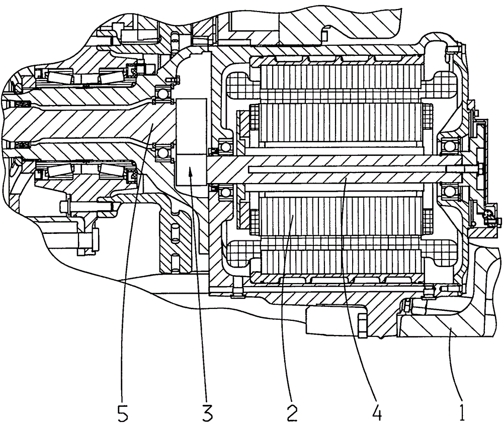
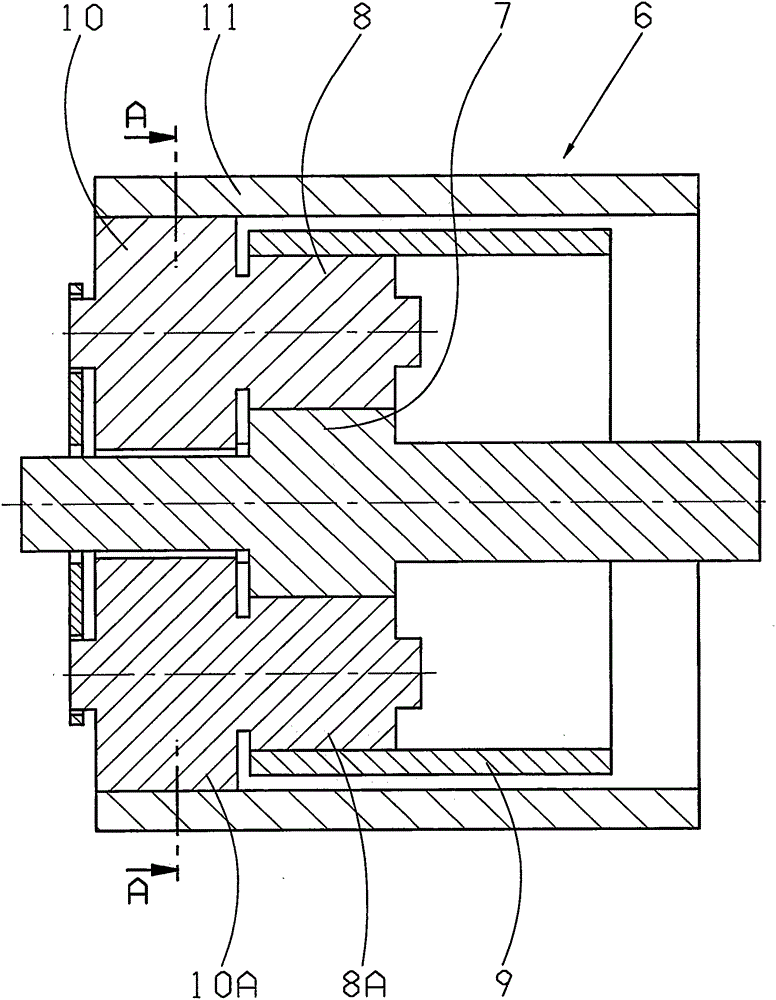
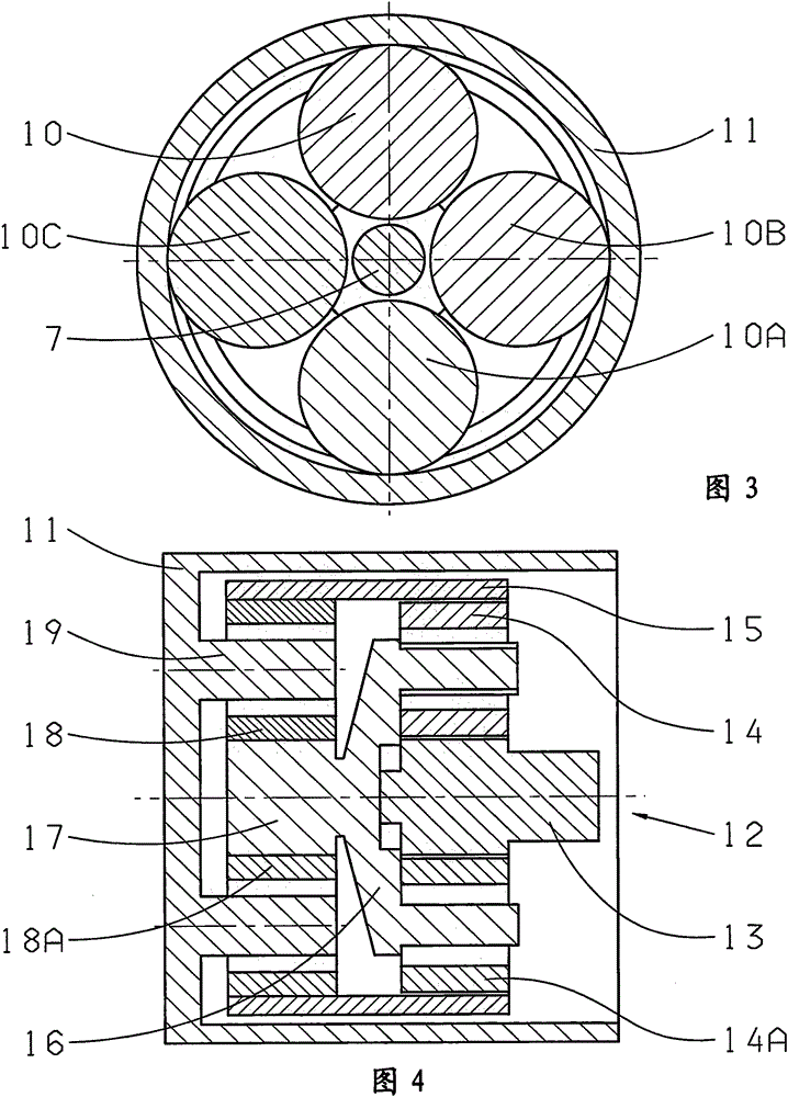
[0019] Various possible variant embodiments of a device according to the invention for driving wheels with at least one drive motor 2 integrated in a drive axle 1 of a vehicle are shown in the drawings by way of example.

[0020] Independently of the individual variant embodiments, in the device described, a drive motor 2 , preferably an electric motor, is connected to a drive stage which is coupled to an output stage as a hub-side output. According to the invention, a spur gear 3 is provided as a drive stage and a planetary gear as an output stage. In this way, the proposed arrangement requires as little installation space as possible, so that the installation space available on the drive shaft 1 can be used for a more powerful drive motor 2 . As a result, the drive power of the driven axle can be increased, so that a further drive axle can be dispensed with in the vehicle if required.

[0021] figure 1 A first variant embodiment of the device is shown, in which a drive mot...


PUM


Abstract

An arrangement for driving a vehicle wheel with at least one drive motor (2) which is integrated into a drive axle (1) of a vehicle is proposed, which drive motor (2) is connected to a drive stage which is coupled to an output stage as wheel-hub-side output, wherein a spur gear mechanism (3) is provided as drive stage and an epicyclic gear is provided as output stage.

Description

technical field [0001] The invention relates to a device for driving wheels of the type defined in detail in the preamble of claim 1 , having a drive motor integrated in the drive shaft of the vehicle. Background technique [0002] A wheel drive for low-floor buses is known, for example, from DE 199 32 587 A1, which has a drive motor arranged eccentrically to the wheel axle. The drive motor drives a reduction gear in the form of a planetary gear as drive stage. The driven gear is meshed with the outer sun gear on the one hand and with other gears which are also meshed with the outer sun gear on the other hand. The output of the planetary gear is connected to the inner sun gear of the planetary stage of the output stage, the planet carrier of which forms the output and is connected to the rim of the wheel to be driven. [0003] In the known wheel drive, a very large installation space is required due to the external sun gear and the bearing housing used for the intermediate...

Claims


Application Information

Patent Timeline
Patent Type & Authority Applications(China)
IPC IPC(8): B60K17/04B60K7/00
CPCF16H1/227B60K2007/0038F16H37/041B60K17/046F16H1/46B60K2007/0061B60K7/0007B60L2220/46F16H1/06B60K7/00B60K17/04F16H1/32
Inventor U·佐尔克
Owner ZF FRIEDRICHSHAFEN AG
Why Eureka
Eureka Blog
Learn More