Driving device fr calendering roller

A transmission device and calender roll technology, applied in textiles and papermaking, winding mechanisms, fiber processing, etc., can solve problems such as gear wear, unfavorable for low-noise equipment, and dirty gear transmissions

Inactive Publication Date: 2007-11-28
MASCHINENFABRIK RIETER AG
View PDF10 Cites 2 Cited by
  • Summary
  • Abstract
  • Description
  • Claims
  • Application Information

AI Technical Summary

Problems solved by technology

This partly caused the area around the gear train to be soiled
Noise levels generated by gear transmissions are detrimental to efforts to create low-noise equipment
Also, during operation, the gears are pressed apart by the cotton passing between the calender rolls, as a result, slippage occurs between the teeth, which can also lead to gear wear

Method used


Image

  • Driving device fr calendering roller
  • Driving device fr calendering roller
  • Driving device fr calendering roller

Examples


Embodiment Construction

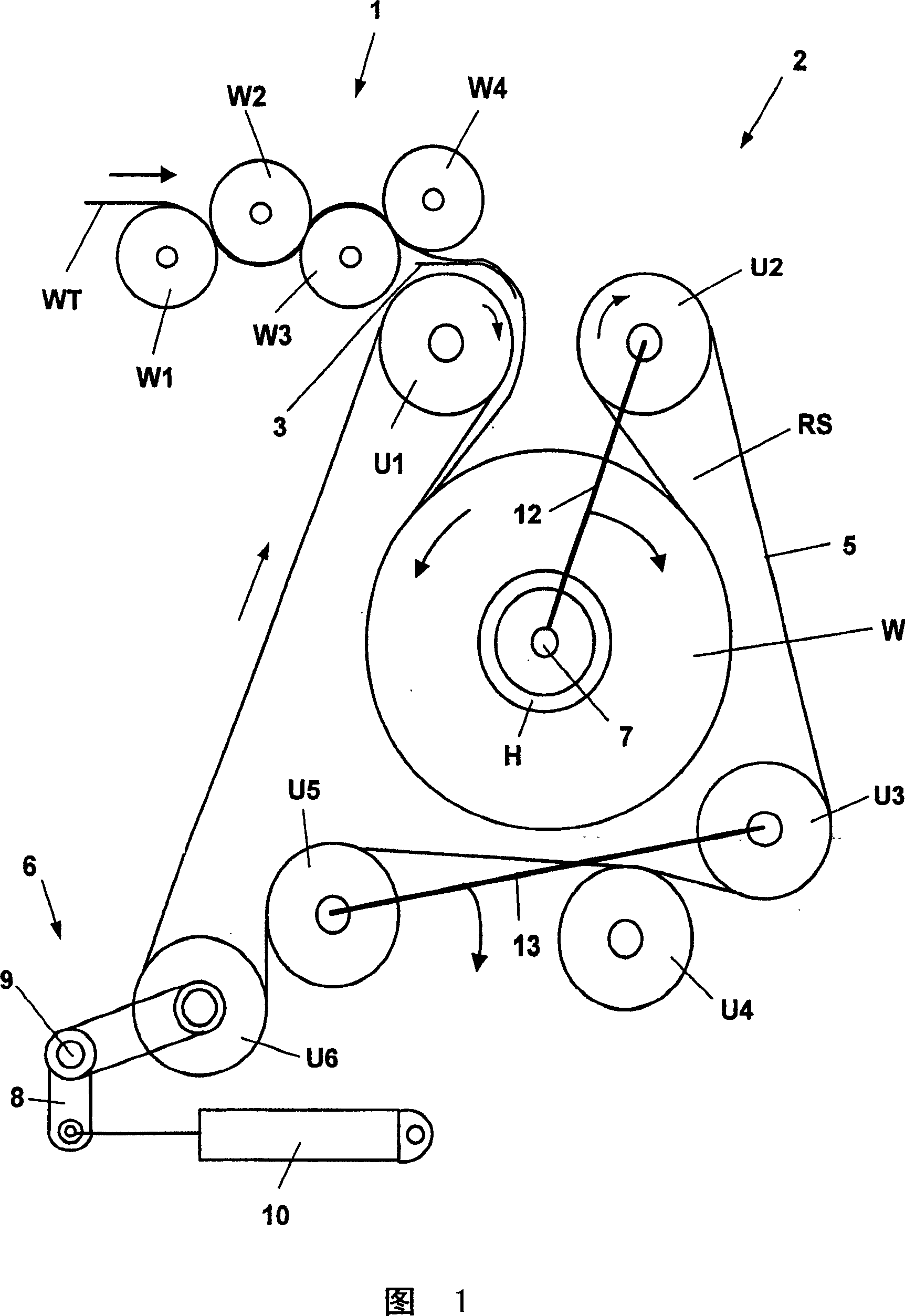
[0025] FIG. 1 shows a set of calender rolls 1 , which set consists of four calender rolls W1 - W4 arranged one behind the other. The calender rolls are arranged slightly offset front and back, between which the cotton WT is transported meanderingly to a subsequent lapping device 2 . Furthermore, the cotton WT passes through a ramp 3 between two deflection rollers U1 and U2, below which there is a belt loop RS of a belt 5 which is guided by other deflection rollers U3, U4, U5 and U6. A small roll W is formed in the belt loop RS, in which the cotton WT is wound on a sleeve H. The sleeve H is supported rotatably about an axis 7 by means of a transverse bearing not shown in detail. Tensioning of the belt 5 of the lap forming device 2 takes place by means of deflection rollers U6 which are arranged rotatable via a double-arm lever 8 in relation to a rotational axis 9 . Double arm lever 8 bears the active force of a cylinder 10 installed in the frame.

[0026] After the small rol...


PUM


Abstract

An assembly compresses and feeds a fleece web to a processing station (2) via three or more calender drums (W1-4) coupled to a drive system (M1, Z6, R). Each drum axle (A1-4) esp. has a pulley wheel (Z1-Z4) with a belt (R) linked to a second pulley wheel (Z6) with drive (M1) motor. The belt (R) follows a snake-like route around the pulley wheels (R1-4) and is adjusted by a tension-setting device (30, 31, 33, RS). The tension setting device is coupled to a tension-correction unit (ST).

Description

technical field [0001] The invention relates to a device for compacting cotton sliver and feeding it to a further processing device, which device has at least three calender rolls arranged approximately one behind the other, which are connected at least in their operating position to a drive. Background technique [0002] Such calender rolls are used, for example, in sliver coilers for the production of finishing laps. Here, a sliver is guided meandering between calender rolls arranged one behind the other, and the sliver is wound into small rolls with a sliver coiler. When the sliver passes between the calender rolls, the calender rolls close together so that the fiber material guided between the calender rolls is compacted, or compression of the passing cotton occurs. Calendering of the sliver is used to increase the strength of the cotton so that in subsequent processes such as in the combing machine the fed laps can be unwound again without any problems. However, the u...

Claims


Application Information

Patent Timeline
Patent Type & Authority Patents(China)
IPC IPC(8): D01G27/02D01G23/00D01G27/00
CPCD01G23/00D01G27/00
Inventor V·皮特里尼A·克莱纳
Owner MASCHINENFABRIK RIETER AG
Why Eureka
Try Eureka