Flat knitting machine with weft yarn, warp yarn and/or float yarn clearing and stitch pressing means

A flat knitting machine and warp technology, applied in the field of flat knitting machine control, can solve problems such as collision of flat knitting machine parts

Active Publication Date: 2016-06-29
KARL MAYER STOLL R&D GMBH
View PDF7 Cites 6 Cited by
  • Summary
  • Abstract
  • Description
  • Claims
  • Application Information

AI Technical Summary

Problems solved by technology

Therefore, collisions with knitting machine components moving during knitting may occur

Method used


Image

  • Flat knitting machine with weft yarn, warp yarn and/or float yarn clearing and stitch pressing means
  • Flat knitting machine with weft yarn, warp yarn and/or float yarn clearing and stitch pressing means
  • Flat knitting machine with weft yarn, warp yarn and/or float yarn clearing and stitch pressing means

Examples


Embodiment Construction

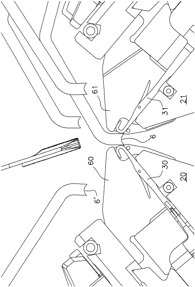
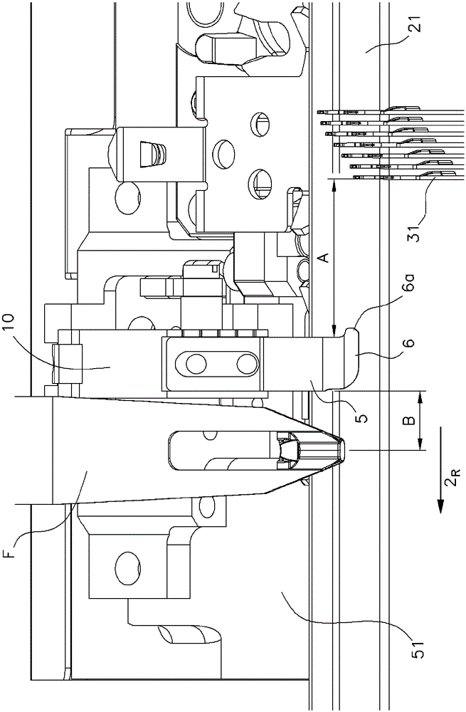
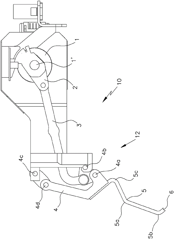
[0036] figure 1 A view is shown of a flat knitting machine 100 with front and rear needle beds 20 , 21 , each of which has a needle 30 , 31 mounted thereon for knitting to move back and forth relative to the knockout comb slot KS. Each needle bed 20 , 21 is associated with a triangular carriage 50 , 51 which can move along the needle bed 20 , 21 respectively. A knitting system with triangular base plates 40 , 41 is arranged on the triangular carriages 50 , 51 . The triangular base plates 40, 41 are considered to be part of the loop forming system. A knitting system preferably consists of two cams (front-rear needle beds). On the triangular carriages 50, 51, a plurality of knitting systems can be arranged front and back as viewed in the direction of movement of the triangular carriages 50, 51. Triangles for transmitting movement to the needles 30 , 31 are mounted on triangular bases 40 , 41 . The yarn feeder F is used to supply the yarn G to the needles 30,31. figure 1 Onl...


PUM


Abstract

The invention relates to a flat knitting machine, which has at least one needle bed (20, 21) and a cam carriage (50, 51) movable along the needle bed (20, 21), on which at least one Knitting system, wherein on the carriage (50, 51) there is provided a loop for unknotting weft, warp and / or floating yarn and / or inserting it into the knitwear and / or for holding the knit while knitting. A device (10) for a product, and the yarn contact area of ​​the device (10) is arranged at one end of the knitting system and outside the knitting system.

Description

technical field [0001] The invention relates to a flat knitting machine, which has at least one needle bed and a carriage movable along the needle bed, on which at least one knitting system is arranged, wherein the carriage is provided with a Device for delooping and / or inserting weft, warp and / or float yarns into the knitted fabric and / or holding the knitted fabric during loop formation. [0002] The invention also relates to a flat knitting machine control method. Background technique [0003] In order to impart prescribed properties in terms of increased or reduced stretchability in the complete knitwear or in partial areas of the knitwear to endow knitted manufactures with additional yarn material during the manufacture of the actual course it is known The area joins knitwear. They can be weft yarns, or also floating yarns, which are introduced into the knitting process by means of special thread guides, where, depending on the desired effect, e.g. elastane yarns are u...

Claims


Application Information

Patent Timeline
Patent Type & Authority Applications(China)
IPC IPC(8): D04B7/14D04B15/36D04B7/04
CPCD04B15/90
Inventor L.菲尔斯特W.伦普R.彦特M.巴林格
Owner KARL MAYER STOLL R&D GMBH
Why Eureka
Try Eureka