Terminal insertion apparatus

Active Publication Date: 2009-03-12
YAZAKI CORP
View PDF2 Cites 17 Cited by
  • Summary
  • Abstract
  • Description
  • Claims
  • Application Information

AI Technical Summary

Benefits of technology

[0015]According to the present invention, the control device reciprocates the connector housing in the two directions, which are orthogonal to one another, intersecting the insertion direction in order to prevent the terminal from hitting the inner surface of the terminal receiving chamber and achieve the assured insertion of the terminal.
[0016]According to the present invention, the control device stores the move distance of the terminal in the terminal receiving chamber of the connector housing having the respective

Problems solved by technology

In the worst case, the insertion head bends the electrical wire 1

Method used


Image

  • Terminal insertion apparatus
  • Terminal insertion apparatus
  • Terminal insertion apparatus

Examples


Embodiment Construction

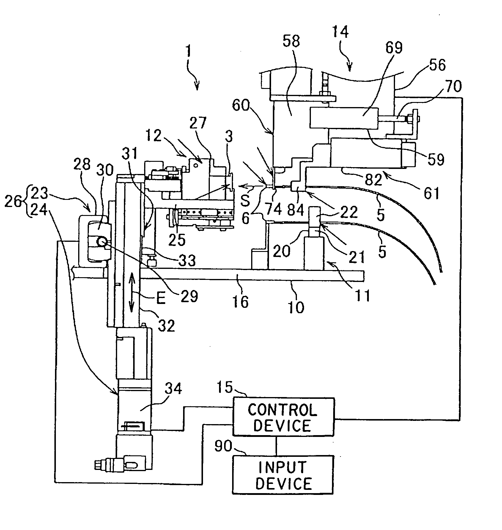
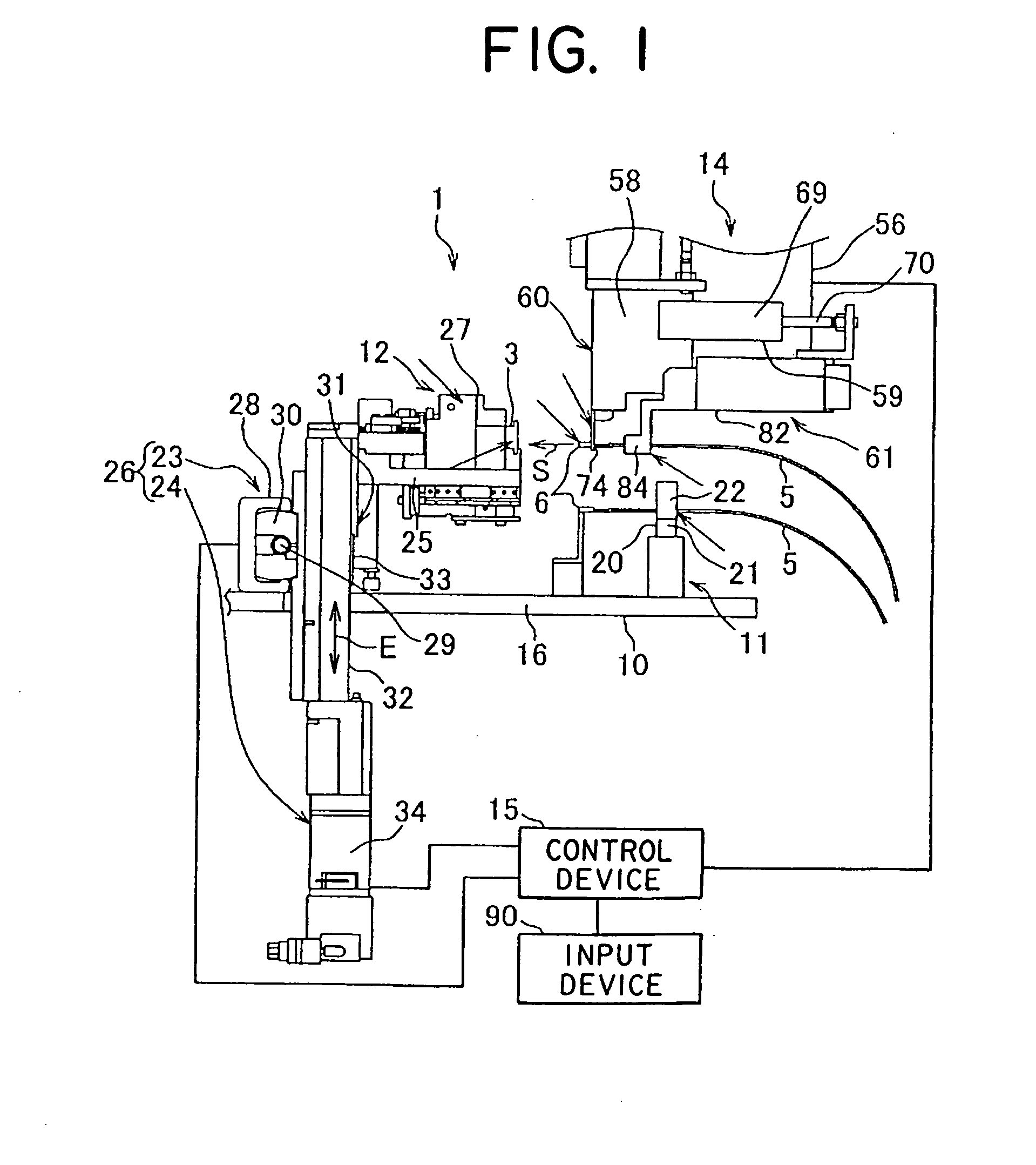
[0028]An embodiment of a terminal insertion apparatus of the present invention is illustrated in FIGS. 1-6. A terminal insertion apparatus 1 of FIG. 1 inserts a terminal 6 connected with an electrical wire 5 into an associated terminal receiving chamber 4 of a connector housing 3, shown in FIG. 2, with a variety of part numbers.

[0029]The connector housing 3, which is made of an insulation synthetic resin and formed in a rectangular shape, includes the plurality of the terminal receiving chambers 4 passing through the connector housing 3. The terminal receiving chambers 4 each receive the associated terminal 6 connected with an electrical wire 5 having a conductive core and an insulation sheath.

[0030]A connector having the connector housing 3 is fitted to a mating connector to configure a wiring harness in a motor vehicle. Either of the terminal receiving chambers 4 or the terminals 6 have locking arms to be locked together so as to hold the terminals 6. The terminal receiving chambe...


PUM

PropertyMeasurementUnit
Distanceaaaaaaaaaa

Abstract

The present invention is to provide a terminal insertion apparatus to insert a terminal into a terminal receiving chamber without hitting an inner surface of the terminal receiving chamber. A terminal insertion apparatus includes a housing holder unit, an insertion unit, and a control device. The housing holder unit holds a connector housing and is movable in a horizontal direction and a vertical direction. The insertion unit inserts a terminal attached with an electrical wire into a terminal receiving chamber of the connector housing. The control device controls a move unit support portion to reciprocate a housing holder by a move distance after an end portion of the terminal is inserted into the terminal receiving chamber so that the terminal can be inserted without hitting an inner surface of the terminal receiving chamber.

Description

BACKGROUND OF THE INVENTION[0001]1. Field of the Invention[0002]The present invention relates to an apparatus for inserting a terminal connected with an electrical wire into a terminal receiving chamber of a connector housing.[0003]2. Description of the Related Art[0004]A variety of terminal insertion apparatus (for example, JP 2006-92841 A) has been utilized to insert a terminal 103 connected with an electrical wire 102 into a terminal receiving chamber 101 of a connector housing 100 to be assembled into a wiring harness of a motor vehicle.[0005]The terminal insertion apparatus includes a main body, a housing holder, a wire holder, and an insertion head. The main body is installed on a floor of a factory and the housing holder is attached to the main body to hold the connector housing 100. The wire holder holds the electrical wire 102 attached with the terminal 103. The insertion head removes the electrical wire 102 from the wire holder and inserts the terminal 103 into the termina...

Claims


Application Information

Patent Timeline
IPC IPC(8): B23P19/00
CPCH01R43/20Y10T29/53261Y10T29/49174Y10T29/5193Y10T29/53239
Inventor FURUYA, HIROSHISUGIMURA, KAZUHIKO
Owner YAZAKI CORP
Why Eureka
Try Eureka